Cowboy Programming Game Development and General Hacking by the Old West

January 5, 2007

Parallax Mapped Bullet Holes

Filed under: Game Development,Inner Product — Mick West @ 1:35 pm

This article was originally published in the “Inner Product” column in Game Developer Magazine, May 2006

Download the shaders, models, textures and maps:
DOWNLOAD
630K

A common effect in video games is some kind of damage being applied to walls and other surfaces when they are shot, usually by the player. This effect makes the player feel like they are actually affecting the environment around them, and makes the simple act of shooting a wall somewhat satisfying.

In an idea situation, when the player shoot the wall, chunks of the wall would fly off, leaving actual holes in the wall, eventually the wall would be chipped away until it falls to rubble in front of you. Unfortunately implementing such a general purpose solution is very complex and expensive, since it requires the creation of arbitrary amounts of new geometry and possibly textures.

DECALS

A more common technique is to apply a decal to the wall. A decal is a two dimensional image of some damage, such as a bullet hole, that is pasted in some way over the surface of the environment geometry. Decals are also used for other player instantiated modifications to the world, such as spraying graffiti and blood spatters.

There are several ways of implementing decals. You can create a new quad that is aligned with the wall surface with the decal texture face mapped to that quad. You can make a copy of a section the wall geometry, and position the decal by adjusting UV coordinates. You can apply the decal as an additional rendering pass on the original geometry.

Each of these methods has their pros and cons, and the method you use will depend on what you generally use decals for. For bullet holes it’s useful to have an arbitrary number of holes scattered around (since you will want to spay bullets all over the wall). In this situation it’s probably best to create a new quad for each new bullet hole.

PARALLAX MAPPING

The problem with decals is that they are two-dimensional. While this works fine for graffiti and blood splats, the player expects a bullet hole to have some depth, so a flat image of a bullet hole is less than convincing. The solution here is to use a pixel shader technique called “parallax mapping” to give the illusion of depth to a 2D texture.

Parallax mapping is a surprisingly simple technique, but can be quite difficult to visualize exactly how it works. Basically we store a per-pixel depth map for the decal texture, then for each pixel rendered, we offset the UV coordinates based on the depth at that pixel, and the view vector. This is best explained with a working example.

CREATING THE ASSETS

First we need a bullet hole. Initially we create a detailed 3d textured model (see figure 1). This model is excessively detailed, over 1000 polygons. But that’s not important, as we are only using it to generate our decal texture and the depth map.

Diffuse
classs=
Figure 2 – Diffuse Map and Alpha channel
 

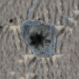
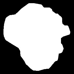
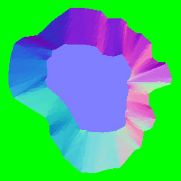
From the model, we render the diffuse map (figure 2a), which contains an alpha channel that matches the outline of the hole (figure 2b). We also render a normal map (figure 3a), which has a depth map in the alpha channel (figure 3b). A combined normal and depth map is often referred to as a “relief map” .

There are a number of different ways of generating the depth and normal maps. You could draw the depth map by hand. If you look at figure 3b, you can see it is fairly simple. The wall surface is black, a depth value of zero. The flat bottom of the bullet hole is white, a depth value of 255 (which is 1.0 in the shader, see later). The walls of the bullet hole are a smooth gradient from black to white. You could draw this depth map roughly by hand, and then generate the normal map from the depth map using any one of several free tools.

Diffuse
classs=
Figure 3 – Normal Map and Depth Map
 

However you’ll get better results if you generate the depth map and the normal map directly from a 3D model. I generated the examples show using 3D Studio Max, and the “Render to Texture” function to generate a matching pair of diffuse map and relief map from the high resolution model. All of the assets I use here, together with the shader code, can be downloaded from gdmag.com.

DOING THE MATH

When rendering a triangle at the pixel level, consider a point P on that triangle. If we were rendering a triangle in the ordinary manner, then that point would have uv coordinates associated with it, and also we would have the view vector v. Given the uv coordinates, we would normally just sample the texture and then use this color to apply lighting, etc. Instead, with parallax mapping we perform a number of very simple additional steps:

1) Read the depth at this uv coordinates
2) Transform the view vector into tangent space
3) Scale the view vector by the depth we just read
4) Add the x and y components to the u and v coordinates
5) Use the new uv coordinates.

The math here is very simple. The most complex sounding part is step 2, transforming the view vector into tangent space. The view vector is the vector from the camera to the pixel in view space (meaning the camera rotation has already been applied by the vertex shader). Tangent space is a coordinate system defined by three basis unit vectors: the normal, binormal and tangent vectors. These basis vectors can vary per pixel. To translate into tangent space, you form a rotation matrix from the basis vectors and then multiply the vector by this.

When we have the view vectors in tangent space, we have the situation shown in figure 4. This shows a cross section of the bullet hole. The point we are rendering is P, the view vector in tangent space is v. Since this is a cross-section, you can’t see the y component, so we are only looking at the x component (left to right) and the z component (up).


Figure 4 – Ofsetting the source pixels by the view vector scaled by the depth

At the point P, we read the depth of the bullet hole d. The view vector is normalized, and then scaled by d, (and by an arbitrary constant you can use to make holes deeper or shallower). The resultant vector is then added to the uv coordinates from point P, ignoring the Z component, which gives us the uv coordinates for a new virtual point P’. (Note in figure 4, v is a vector, and d is just the scalar depth, not a vector).

It is important when trying to visualize what is going on here that you realize that the points that we render do not themselves move around. All that is happening is that we are adjusting the uv coordinates of the point P so they match the uv coordinates of P’. P is still rendered at position P, just with the uv coordinates of P’. Think of it as the point you are rendering pulling its texture from a bit further away. The greater the depth and the greater the angle between the view vector and the surface, the greater the distance from the rendered point to the actual point used in the texture.

MODIFYING THE SHADERS

Listing 1 – modifying the uv coordinates in the pixel shader

// Given the regular uv coordinates
float2 uv = IN.TexCoord0*tile;  

      // Step 1 - Get depth from the alpha (w) of the relief map
	float depth = (tex2D(reliefmap,uv).w) * hole_depth;    

	// Step 2 - Create transform matrix to tangent space
	float3x3 to_tangent_space = float3x3(IN.binormal,IN.tangent,IN.normal);
                              
	// Steps 2 and 3
      float2 offset = depth * mul(to_tangent_space,v);        

      // Step 4, offset u and v by x and y
	uv += offset;

Listing 1 shows the actual implementation of this extra processing in a pixel shader. The view vector, the uv coordinates and the basis vectors are passed to the pixel shader by the vertex shader. The remaining code in the pixel shader is exactly the same as a regular pixel shader in terms of lighting, etc. All that is added are the steps above, which modify the UV coordinates.

RESULTS

The word “parallax” refers to the effect where objects that are closer to the viewer move more than object that are at a greater distance, when the viewer moves their position at right angles to those objects. As such, the parallax effect is best appreciated in motion. Figure 5 shows the bullet holes mapped onto a plane with and without parallax mapping. Figure 5a shows the bullet holes rendered in the normal manner. Figure 5b shows them with parallax mapping. In these static images there is not so much difference, but note how the closer sides of the hole have shrunk, and the far sides have grown.


Figure 5a – Standard bump mapping


Figure 5b – Parallax mapping

SIMPLE OCCLUSION

Parallax mapping is a simple technique, which means that it’s relatively cheap, and it’s compatible with more graphics cards than a ray-casting solution. However, it is still only a very approximate mapping to what you would actually want to see on screen, and suffers from a number of problems. The most obvious of these is that there is no occlusion. You can always see all of the texture, it is just distorted. In addition, as the texture shifts around, there is more distortion as the base of the bullet hole seems to climb partially up the sides of the hole.

In the general case of parallax mapping, there is no cheap solution to this; you would need to do some iteration in your shader. However, in the rather specific case of a basically concave bullet hole with a flat base we can make certain assumptions that allow us to greatly improve the appearance without an excessive performance hit.

Firstly we note that the base of the bullet hole has a constant depth value of 1.0. We’d like the base of the hole not to be distorted, and to be properly occluded. We can do this by first assuming the point P has a depth of 1.0, then finding the modified uv. If this then also has a depth of 1.0, then we know that this ray actually intersects the base of the hole, regardless of the depth at point P. If it does NOT, then we re-calculate the offset using the depth at point P. Occlusion is then taken care of by the base pixels sliding behind the alpha mask. The relative movement of the base also becomes more realistic.

To implement this modification, we remove the initial lookup of depth, and replace the calculation of the offset with Listing 2. This takes our pixel shader from 35 to 40 instructions on a GeForce 6800 GT (including lighting.)

Listing 2 – occluded base

        float2 offset = hole_depth * mul(to_tangent_space,v);        
        if (tex2D(reliefmap,uv+offset).w < 0.96)
        {
           offset *= (tex2D(reliefmap,uv).w);          
        }

LESS DISTORTION

Things now look a little better, however we still have a problem with the texture streaking when viewed from extreme angles, especially near the rim of the hole on the side further away from the viewer. The problem here is that the depth at point P is 1.0, yet the ray actually intersects the rim fairly close to the top, where P is closer to 0.1. We can get a surprisingly effective improvement here simply by averaging the two depth values we read earlier. Again this is a simple and cheap modification, requiring no iterations, and only adds 2 instructions to our shader.(Listing 3).

        float2 offset = hole_depth * mul(to_tangent_space,v);        
        float depth_at_1 = tex2D(reliefmap,uv+offset).w;
        if ( depth_at_1 < 0.96f)
        {
             offset *= (depth_at_1 + (tex2D(reliefmap,uv).w)) * 0.5;          
        }

PROBLEMS YOU MIGHT ENCOUNTER

The biggest problems I had in implement this were in ensuring the coordinate systems were consistent. The coordinate systems used by 3D Studio Max and DirectX are right handed and left handed respectively. Moving from one to the other requires changes in the shader. Specifically I had to change the order of the basis vectors to make the tangent space calculation come out right.

The height map we use here is actually a depth map, ranging from 0.0 to 1.0 units into the plane of the texture. Many implementations of parallax mapping map the range 0.0,1.0 to -1.0,1.0, to allow for features raised above the plane of the texture. Here we are implementing a specific shader for bullet holes, so be aware of this different when looking at other code.

You might also have problems with the sign of the height map and the normal maps. You can flip these in the shader, but it's more effective to get them right the first time, which you can quickly test by inverting components of the maps in Photoshop.

CONCLUSIONS

We can get quite realistic looking bullet holes using a relatively simple and inexpensive pixel shader. While it does not give us the full occlusion of an iterative approach, it is both quicker, and more likely to run on older graphics cards. By writing a shader specifically for a particular kind of topography, we are able to adjust the algorithm to give more pleasing results without worrying about the general case.

RESOURCES

Tomomichi KANEKO, et al, Detailed Shape Representation with Parallax Mapping, 2001, http://vrsj.t.u-tokyo.ac.jp/ic-at/ICAT2003/papers/01205.pdf
Terry Welsh, Parallax Mapping with Offset Limiting, 2004, http://www.infiscape.com/doc/parallax_mapping.pdf
William Donnelly. Per-Pixel Displacement Mapping with Distance Functions, 2005, http://download.nvidia.com/developer/GPU_Gems_2/GPU_Gems2_ch08.pdf

Multithreading Particle Sytems

Filed under: Game Development,Inner Product — Mick West @ 12:16 pm

OPTIMIZING A PARTICLE SYSTEM FOR MULTI-CORE ARCHITECTURE

This article was originally published in the “Inner Product” column in Game Developer Magazine, April 2006

Download the sample application:
DOWNLOAD
229K

In my February column I discussed the various ways you might extend a game engine to take advantage of multi-core processing. On method mentioned was “Forking from a single thread. In this month’s column I’m going to discuss how this is implemented in practice to speed up the processing of a particle system. I’ll present the code needed to get multi-threaded processing working, and then benchmark various approaches and configurations.

PARTICLE SYSTEM

Particles systems are very common in games. They consist of a large number of small objects that each has a low memory and processing overhead, allowing you to get a very large number of objects on screen. Particle effects are used to simulate fire, smoke, explosions and various other physical effects.

In the example code (available online at gdmag.com) I implement a simple 2D particle system that nonetheless performs a significant amount of processing per particle, including a collision check to allow the particle to interact with the environment. The test case simulates 80,000 particles. particle_screen.jpg

My test machine has a 3.2 GHz dual core Pentium 4 Extreme Edition with hyper-threading enabled. This configuration gives us four hardware threads. In theory this should enable us to run code up to 2.6 times as fast as a regular single core, non-hyper-threaded CPU. The Figure of 2.6 is arrive at by a theoretical 100% speed increase from using two cores, followed by a 30% increase from hyper-threading. In real-world tests, I actually got a 3.0x speed increase, slightly better than expected.

THE CODE

I have attempted to make the code duplicate what you might find in a real game engine. There is a particle class, which has an update() function. There is an array of particles, and a count of particles. To update the position of the particles, the particle manager code simply iterates over them and calls their update() function (listing 1).

Listing 1:

for (int i=0;i<n;i++)
	{
		mp_particles[i].Update(update_time);
	}

The update code itself moves the particle, and checks for collision with the environment, and updates the color of the particle based on the speed. (Listing 2). This is a fairly significant amount of code to be executed per particle.

Listing 2:

void CParticle::Update(float time)
{
	m_old_pos = m_pos;
	Vector2 pos2 = m_pos + m_vel * time;
	Vector2 to = m_pos - Vector2(x,y);
	float force = 1000.0f/to.Length2();
	m_vel += to * force;
	m_vel -= m_vel * 0.03f;
	m_color = 0xff800000 + (int)m_vel.Length();
	if (whisker.CheckCollision(m_pos, pos2)) 	{
		m_pos = whisker.GetPoint() + 0.01f * whisker.GetNormal();
		m_vel = m_vel - 2.0f * DotProduct((m_vel),whisker.GetNormal()) * whisker.GetNormal();
	} else {
		m_pos = pos2;
	}
}

This type of processing is an ideal candidate for parallel processing. The order of processing the particles is unimportant, since they do not interact with each other. The particle processing does not use any common resources. The method of processing by stepping through an array can easily be broken into sub-sections of the array.

FORKING

So the first thing I tried was forking threads to process the particles in groups. To do this the particle manager’s update loop changed from Listing 1, to Listing 3.

Listing 3:

for (int t=0;t<MAX_THREAD;t++) {
  ThreadIndex[t] = t;
  thThread[t] = CreateThread(NULL,0,thParticleUpdate,(LPVOID)&ThreadIndex[t],0,&threadId);
}
WaitForMultipleObjects(MAX_THREAD,&thThread[0],true, INFINITE);
for (int t=0;t<MAX_THREAD;t++) {
  CloseHandle(thThread[t]);
}

This creates MAX_THREADS threads, which immediately begin executing. The main thread then waits at the call to WaitForMultipleObjects until all the threads are finished.

The value in MAX_THREADS should match the number of hardware threads your system is capable of supporting. In our case the optimal value is four, but we perform tests with one, two, three and four threads.

The thread that is created calls the function thParticleUpdate, shown in Listing 4. This divides the particles up into chunks based on the thread number. With four threads, the first thread will process particles, 0-19999, the second 20000-39999, the third 40000-59999 and the fourth 60000-79999.

Listing 4:

DWORD WINAPI thParticleUpdate(LPVOID p)
{
	int thread = *(int*)p;
	float time = update_time;
	int n = g_ParticleManager.m_num_particles;
	int step = n / MAX_THREAD;
	int start = step*thread;
	int end = step*(thread+1);
	if (thread == MAX_THREAD-1) end = n;
	for (int i=start;i<end;i++)	{
		g_ParticleManager.mp_particles[i].Update(time);
	}
}

WORKER THREADS

Since creating a thread incurs some overhead, it is best not to create threads every time we need to fork. Instead we can get functionally the same results by creating the threads upon program initialization, and then using events to signal the thread to start and indicate when it has stopped. This approach is known as using “worker threads” . The particle manager update function then just reduces to signaling the thread start events, and then waiting for the events to finish (Listing 5).

Listing 5

for (int t=0;t<MAX_THREAD;t++)
	SetEvent(thStartThreading[t]);
WaitForMultipleObjects(MAX_THREAD,&thStopThreading[0],true, INFINITE);

The threads themselves are initialized at startup, along with the arrays of events used to signal a thread to start, and for the threads to signal that they have completed (Listing 6)

Listing 6

for (int t=0;t<MAX_THREAD;t++){
    ThreadIndex[t] = t;
    thStartThreading[t] = CreateEvent(NULL, FALSE, FALSE, NULL);
    thStopThreading[t]  = CreateEvent(NULL, FALSE, FALSE, NULL);
    thThread[t] = CreateThread(NULL,0,thParticleUpdate,(LPVOID)&ThreadIndex[t],0,&threadId);
}

Then the function thParticleUpdate needs to be modified, so that instead of being a one-shot function, it is now a loop that continually executes the same piece of code whenever the thStartThreading flag is set. (Listing 7).

Listing 7:

DWORD WINAPI thParticleUpdate(LPVOID p)
{
	int thread = *(int*)p;
	while (1)
	{
		WaitForSingleObject(thStartThreading[thread],INFINITE);
		/* ”¦ BODY OF FUNCTION ”¦ */
		SetEvent(thStopThreading[thread]);
	}
}

MORE REALISM

In order for the tests to be more realistic, I also wanted to run them as if there was a physics engine taking up the majority of the processing time in a single thread. So I added another thread that just constantly multiplied two numbers together and stored the result (listing 7)

Listing 7:

float dummy_a = 1.1f;
DWORD WINAPI DummyThread(LPVOID p)
{
	while (dummy_a != 0)
		dummy_a *= 1.00001f;
	return 0;
}

This was then run in a separate thread. It’s not an ideal test, as it just constantly does work, rather than a fixed amount of work. But it roughly simulates the case where you can keep a thread busy for an entire frame.

RESULTS

I tested three software configurations: Forked threads, Worker threads and worker threads plus physics. Each of these configurations was tested with 1,2,3 and four processors, and the results were converted into a percentage of the time taken to update the particles in the normal manner (listing 1). The code was timed both for how long it took to update the logic (columns L1, L2, etc), and how long it too to execute a whole frame. (F1, F2, etc). Smaller numbers indicate less time taken, and hence faster.

After running in three different software configurations, I did three different hardware configurations. The test machine allowed me to disable both dual core and hyperthreading via the bios, so I tested with all three possible combinations. The Results are shown in table 1.

ANALYSIS

As we expected, the fastest execution is with four worker threads. The particle system is updated in one third of the time taken by the unthreaded approach. The frame rate is almost doubled – although in this test, the particle system takes up 2/3 of all CPU time.

The difference between using forking threads and using worker threads is very striking, with the worker thread approach being about 12% faster than using forked threads. This is presumably due to the overhead in creating a new thread. Whenever a thread is created, it needs memory allocated, including a default 1MB for the stack. This, and other overhead, makes constantly creating and destroying threads a drain on resources.

With the dummy physics thread in the mix, we see some slowdown, but really not as much as you might think, considering the dummy thread should be hogging 100% of one of the cores, leaving just the 30% hyperthread capacity, and the other processor. So why do we only see a slight drop in performance?

The answer is the windows scheduler is attempting to spread the work evenly amongst the threads, which means that it will constantly preempt the dummy thread in order to let the worker threads (and the main thread) execute. That’s why a simple loop is not a good test load. A more realistic dummy physics load would be to execute the loop a fixed number of times, and have the main thread stall until the dummy thread finishes each frame.

LESS CORES

Generally the fewer cores you have, the lower your performance. One initially surprising result was that by disable hyper-threading, the performance of the single threaded version actually improved slightly, with the framerate increasing 4%. This shows that if code is not specifically written with hyperthreading in mind, then enabling hyperthreading can actually hurt performance slightly. Some PC vendors allow you to choose your PC to be shipped with hyperthreading disabled.

This is unfortunate, as the potential is there for hyperthreading to greatly improve performance, and it would be a shame is people switched it off just because some games ran slowly with it enabled. Indeed, with a single core, and hyperthreading enabled, we get a very significant 24% improvement in framerate with two threads.

One interesting result is whenever there are two logical CPUs (either single core with hyperthreading, or dual core with no hyperthreading), then the performance drops drastically when moving from two threads to three threads. This is because we can now only execute two threads simultaneously. Since the execution time of a single worker thread is short, the task scheduler will not be able to share the work evenly, and so the first two threads might run to completion before the third thread even starts. It then runs with one CPU idle, giving a 25% decrease in performance. If the task were one that ran much longer, then the overhead of having three threads for two CPUs would be much less. Running four threads is only slightly slower than two threads as the work can be evenly divided.

CONCLUSIONS

Optimizing simple systems for multi-core and hyperthreaded machines is very straightforward, and yields very impressive results. Using worker threads instead of forked threads means that there is very little overhead in splitting up a task, and performance increases can be had even on systems with a relatively small number of objects.

The windows task scheduler usually does a good job of farming out the work to available processors. While you can force a particular thread onto a particular CPU using the SetThreadAffinityMask function, I did not see any performance gain from doing this. It might still be worth looking into though, depending on how your engine is structured.

Particle systems are just one of several potential things that could be optimized in this way. Anything that deals with a reasonable number of independent data objects is a candidate. Such things might include: skinning, debris physics, flocking or speech recognition. With appropriate synchronization methods, the multi-threaded approach can be extended to the updating of more complex interdependent objects, such as AI and game logic.

The best performance is gained by scaling your threads to match the available CPUs. On a fixed target like the Xbox 360, you can specifically target six hardware threads. On the PC, you can attempt to determine the number of CPUs available, but if in doubt, then four threads will generally work well. However you should consider that soon we will have quad-core hyperthreaded (such as Intel’s “Tigerton” ), machines, giving us eight logical CPUs. Ideally your engine should scale to the appropriate number of threads, and not introduce overhead on a single logical CPU machine.

RESOURCES

James Boer, Multithreaded Audio Programming techniques, Game Programming Gems 5, 2005, Charles River Media, Hingham, MA, p697

Intel Corporation’s multi-core articles, http://intel.com/software/multicore

AMD Corporation’s multi-core site: http://multicore.amd.com/en/

Evolve Your Hierarchy

Filed under: Game Development,Inner Product — Mick West @ 11:35 am

Refactoring Game Entities with Components

Up until fairly recent years, game programmers have consistently used a deep class hierarchy to represent game entities. The tide is beginning to shift from this use of deep hierarchies to a variety of methods that compose a game entity object as an aggregation of components. This article explains what this means, and explores some of the benefits and practical considerations of such an approach. I will describe my personal experience in implementing this system on a large code base, including how to sell the idea to other programmers and management.

GAME ENTITIES

Different games have different requirements as to what is needed in a game entity, but in most games the concept of a game entity is quite similar. A game entity is some object that exists in the game world, usually the object is visible to the player, and usually it can move around.

Some example entities:

  • Missile
  • Car
  • Tank
  • Grenade
  • Gun
  • Hero
  • Pedestrian
  • Alien
  • Jetpack
  • Med-kit
  • Rock

Entities can usually do various things. Here are some of the things you might want the entities to do

  • Run a script
  • Move
  • React as a rigid body
  • Emit Particles
  • Play located audio
  • Be packed up by the player
  • Be worn by the player
  • Explode
  • React to magnets
  • Be targeted by the player
  • Follow a path
  • Animate

TRADITIONAL DEEP HIERARCHIES


The traditional way of representing a set of game entities like this is to perform an object-oriented decomposition of the set of entities we want to represent. This usually starts out with good intentions, but is frequently modified as the game development progresses – particularly if a game engine is re-used for a different game. We usually end up with something like figure 1, but with a far greater number of nodes in the class hierarchy.

As development progresses, we usually need to add various points of functionality to the entities. The objects must either encapsulate the functionality themselves, or be derived from an object that includes that functionality. Often, the functionality is added to the class hierarchy at some level near the root, such as the CEntity class. This has the benefit of the functionality being available to all derived classes, but has the downside of the associated overhead also being carried by those classes.

Even fairly simple objects such as rocks or grenades can end up with a large amount of additional functionality (and associated member variables, and possibly unnecessary execution of member functions). Often, the traditional game object hierarchy ends up creating the type of object known as “the blob” . The blob is a classic “anti-pattern” which manifests as a huge single class (or a specific branch of a class hierarchy) with a large amount of complex interwoven functionality.

While the blob anti-pattern often shows up near the root of the object hierarchy, it will also show up in leaf nodes. The most likely candidate for this is the class representing the player character. Since the game is usually programmed around a single character, then the object representing that character often has a very large amount of functionality. Frequently this is implemented as a large number of member functions in a class such as CPlayer.

The result of implementing functionality near the root of the hierarchy is an overburdening of the leaf objects with unneeded functionality. However, the opposite method of implementing the functionality in the leaf nodes can also have unfortunate consequence. Functionality now becomes compartmentalized, so that only the objects specifically programmed for that particular functionality can use it. Programmers often duplicate code to mirror functionality already implemented in a different object. Eventually messy re-factoring is required by re-structuring the class hierarchy to move and combine functionality.

Take for example the functionality of having an object react under physics as a rigid body. Not every object needs to be able to do this. As you can see in figure 1, we just have the CRock and the CGrenade classes derived from CRigid. What happens when we want to apply this functionality to the vehicles? You have to move the CRigid class further up the hierarchy, making it more and more like the root-heavy blob pattern we saw before, with all the functionality bunched in a narrow chain of classes from which most other entity classes are derived.

AN AGGREGATION OF COMPONENTS

The component approach, which is gaining more acceptance in current game development, is one of separating the functionality into individual components that are mostly independent of one another. The traditional object hierarchy is dispensed with, and an object is now created as an aggregation (a collection) of independent components.

Each object now only has the functionality that it needs. Any distinct new functionality is implemented by adding a component.

A system of forming an object from aggregating components can be implemented in one of three ways, which may be viewed as separate stages in moving from a blob object hierarchy to a composite object.

OBJECT AS ORGANIZED BLOB

A common way of re-factoring a blob object is to break out the functionality of that object into sub-objects, which are then referenced by the first object. Eventually the parent blob object can mostly be replaced by a series of pointers to other objects, and the blob object’s member functions become interface functions for the functions of those sub-objects.

This may actually be a reasonable solution if the amount of functionality in your game objects is reasonably small, or if time is limited. You can implement arbitrary object aggregation simply by allowing some of the sub-objects to be absent (by having a NULL pointer to them). Assuming there are not too many sub-objects, then this still allows you the advantage of having lightweight pseudo-composite objects without having to implement a framework for managing the components of that object.

The downside is that this is still essentially a blob. All the functionality is still encapsulated within one large object. It is unlikely you will fully factor the blob into purely sub-objects, so you will still be left with some significant overhead, which will weight down your lightweight objects. You still have the overhead of constantly checking all the NULL pointers to see if they need updating.

OBJECT AS COMPONENT CONTAINER

The next stage is to factor out each of the components (the “sub-objects” in the previous example) into objects that share a common base class, so we can store a list of components inside of an object.

This is an intermediate solution, as we still have the root “object” that represents the game entity. However, it may be a reasonable solution, or indeed the only practical solution, if a large part of the code base requires this notion of a game object as a concrete object.

Your game object then becomes an interface object that acts as a bridge between the legacy code in your game, and the new system of composite objects. As time permits, you will eventually remove the notion of game entity as being a monolithic object, and instead address the object more and more directly via its components. Eventually you may be able to transition to a pure aggregation.

OBJECT AS A PURE AGGREGATION

In this final arrangement, an object is simply the sum of its parts. Figure 2 shows a scheme where each game entity is comprised of a collection of components. There is no “game entity object” as such. Each column in the diagram represents a list of identical components, each row can be though of as representing an objects. The components themselves can be treated as being independent of the objects they make up.

PRACTICAL EXPERIENCE

I first implemented a system of object composition from components when working at Neversoft, on the Tony Hawk series of games. Our game object system had developed over the course of three successive games until we had a game object hierarchy that resembled the blob anti-pattern I described earlier. It suffered from all the same problems: the objects tended to be heavyweight. Objects had unnecessary data and functionality. Sometimes the unnecessary functionality slowed down the game. Functionality was sometimes duplicated in different branches of the tree.

I had heard about this new-fangled “component based objects” system on the sweng-gamedev mailing list, and decided it sounded like a very good idea. I set to re-organizing the code-base and two years later, it was done.

Why so long? Well, firstly we were churning out Tony Hawk games at the rate of one per year, so there was little time between games to devote to re-factoring. Secondly, I miscalculated the scale of the problem. A three-year old code-base contains a lot of code. A lot of that code became somewhat inflexible over the years. Since the code relied on the game objects being game objects, and very particular game objects at that, it proved to be a lot of work to make everything work as components.

EXPECT RESISTANCE

The first problem I encountered was in trying to explain the system to other programmers. If you are not particularly familiar with the idea of object composition and aggregation, then it can strike you as pointless, needlessly complex, and unnecessary extra work. Programmers who have worked with the traditional system of object hierarchies for many years become very used to working that way. They even become very good at working that way, and manage to work around the problems as they arise.

Selling the idea to management is also a difficult. You need to be able to explain in plain words exactly how this is going to help get the game done faster. Something along the lines of:

Whenever we add new stuff to the game now, it takes a long time to do, and there are lots of bugs. If we do this new component object thing, it will let us add new stuff a lot quicker, and have fewer bugs.”

My approach was to introduce it in a stealth manner. I first discussed the idea with a couple of programmers individually, and eventually convinced them it was a good idea. I then implemented the basic framework for generic components, and implemented one small aspect of game object functionality as a component.

I then presented this to the rest of the programmers. There was some confusion and resistance, but since it was implemented and working there was not much argument.

SLOW PROGRESS

Once the framework was established, the conversion from static hierarchy to object composition happened slowly. It is thankless work, since you spend hours and days re-factoring code into something that seems functionally no different to the code it replaces. In addition, we were doing this while still implementing new features for the next iteration of the game.

At an early point, we hit the problem of re-factoring our largest class, the skater class. Since it contained a vast amount of functionality, it was almost impossible to re-factor a piece at a time. In addition, it could not really be re-factored until the other object systems in the game conformed to the component way of doing things. These in turn could not be cleanly refactored as components unless the skater was also a component.

The solution here was to create a “blob component.” This was a single huge component, which encapsulated much of the functionality of the skater class. A few other blob components were required in other places, and we eventually shoehorned the entire object system into a collection of components. Once this was in place, the blob components could gradually be refactored into more atomic components.

RESULTS

The first results of this re-factoring were barely tangible. But over time the code became cleaner and easier to maintain as functionality was encapsulated in discreet components. Programmers began to create new types of object in less time simply by combining a few components and adding a new one.

We created a system of data-driven object creation, so that entirely new types of object could be created by the designers. This proved invaluable in the speedy creation and configuration of new types of objects.

Eventually the programmers came (at different rates) to embrace the component system, and became very adept at adding new functionality via components. The common interface and the strict encapsulation led to a reduction in bugs, and code that that was easier to read, maintain and re-use.

IMPLEMENTATION DETAILS

Giving each component a common interface means deriving from a base class with virtual functions. This introduces some additional overhead. Do not let this turn you against the idea, as the additional overhead is small, compared to the savings due to simplification of objects.

Since each component has a common interface, it is very easy to add additional debug member functions to each component. That made it a relatively simple matter to add an object inspector that could dump the contents of the components of a composite object in a human readable manner. Later this would evolve into a sophisticated remote debugging tool that was always up to date with all possible types of game object. This is something that would have been very tiresome to implement and maintain with the traditional hierarchy.

Ideally, components should not know about each other. However, in a practical world, there are always going to be dependencies between specific components. Performance issues also dictate that components should be able to quickly access other components. Initially we had all component references going through the component manager, however when this started using up over 5% of our CPU time, we allowed the components to store pointers to one another, and call member functions in other components directly.

The order of composition of the components in an object can be important. In our initial system, we stored the components as a list inside a container object. Each component had an update function, which was called as we iterated over the list of components for each object.

Since the object creation was data driven, it could create problems if the list of components is in an unexpected order. If one object updates physics before animation, and the other updates animation before physics, then they might get out of sync with each other. Dependencies such as this need to be identified, and then enforced in code.

CONCLUSIONS

Moving from blob style object hierarchies to composite objects made from a collection of components was one of the best decisions I made. The initial results were disappointing as it took a long time to re-factor existing code. However, the end results were well worth it, with lightweight, flexible, robust and re-usable code.

Resources

Scott Bilas: GDC 2002 Presentation: A Data-Driven Game Object System
http://scottbilas.com/files/2002/gdc_san_jose/game_objects_slides.pdf

Bjarne Rene: Component Based Object Management. Game Programming Gems 5, 2005, page 25.

Kyle Wilson: Game Object Structure: Inheritence vs Aggregation, 2002, http://gamearchitect.net/Articles/GameObjects1.html

Multi-core Processors

Filed under: Game Development,Inner Product — Mick West @ 10:19 am

This article originally appeared in the “Inner Product” column in Game Developer Magazine, February 2006

Next generation game platforms are increasingly making use of multiple processors to deliver more computing power. The Xbox 360 has three symmetrical CPUs running two hardware thread each. The PS3 has one master CPU with seven separate “SPE” processors. The Nintendo Revolution is probably dual threaded. Newer gaming PCs have dual core hyper-threaded processors.

Programmers who were used to programming for a single core are now increasing faced with the challenge of translating their programming skills to a multi-core system. Ideally you want to fully utilize the power of all the processors that you have available to you. A processor idling is a processor wasted. In this article I describe some of the issues involved with this, and discuss a few potential ways developers might architect their engines to more fully utilize the potential processing power.

DON’T DO IT?


The simplest option is to just ignore the additional CPU resources, and run all your code from a single thread on a single CPU. (See Figure 1).

All the examples will use this simplified version of the systems in a game engine. Note that the “rendering” portion here is the CPU contribution to rendering (things like high level visibility determination, and preparing the data stream for the GPU to process). The GPU processing is not shown.

Here the flow of execution is very straightforward. We have the game physics, followed by the game logic, and finally the CPU contribution to rendering. Each of these very high-level tasks also has a strict order of mid-level tasks. The physics, for example, first processes the rigid bodies, then the IK animation, and finally the particle systems. This set of systems here is roughly what you might find in a current single processor game.

While this option is obviously not going to take advantage of any of the additional processing power, it does greatly simplify the task of programming the game. Whether this is the best choice depends very much on the type of game you are programming, your schedule, and the programming resources available to you.

Remember the GPU is still responsible for a large portion of the visual quality of your game. If the game contains a relatively low amount of moving and interacting objects (such as a golf game), then you may well be able to get away with using a single processor.

The decision to go single threaded can also greatly simplify the debugging process. Multi-threaded programs can be very difficult to debug. If your schedule is short, and if you’re already got a single-threaded code-base up and running, then it may well be cost effective to simply ignore the extra CPUs, at least for this version of the game.

MANUALLY THREADED TASKS


Some mid level tasks are sufficiently decoupled that they can be executed in any order, and even in parallel. If you are able to identify two such tasks, then in theory you should be able to save the processing time that would be taken up by the shorter of the two tasks, by running the two tasks in parallel. (Figure 2)

Here we see the second core has been partially utilized. The rigid body physics and the IK animation are now running concurrently. The time saved here is again the shorter of the two tasks (the IK animation).

The logic portion of the pipeline is not threaded. Typically things such as AI and game object logic are very dependent on the order of execution, and so it is difficult to split an existing AI system into separate threads without introducing a large number of interesting bugs.

Rendering also has some parallelism shown, with the object rendering running at the same time as the environment rendering.

This approach of selectively shifting certain large tasks into separate threads (and onto separate CPU cores), is something you might do as a quick and easy step when retro-fitting an existing engine to be take advantage of multiple cores. The implementation will vary greatly according to the dependencies between systems in your engine. For example, it might be impossible to perform environment rendering at the same time as object rendering if they both share some resource, such as a pool of vertex buffers, which is not thread safe.

The disadvantage is that your have a fairly limited number of pieces of processing with which to play. There are very few ways in which you can arrange things so that your engine will still work, and hence you will end up making poor use of the second CPU core.

Since the parallel tasks are doing very different things, you will also not be making the best use of your shared cache on a hyper-threaded system.

FORKING FROM A SINGLE THREAD

If your high level systems are not suitable for running in parallel, then you should turn to the low level. Many systems comprise of running a similar piece of code over a large number of objects. If the order of processing of the objects is not important then you can start a very short-lived second thread to process half the objects.

You can visualize this as your main thread “forking” into two (or more) threads, each thread processing some of the data, and skipping over unprocessed data, until all the data is processed. The forked thread(s) then terminate, leaving the main thread to continue along the normal path of execution.


Figure 3 shows how the flow of execution works. The main thread in Core 1 is identical to our simplistic single threaded “solution” in Figure 1. The only difference is that when the main thread is able to process a number of objects concurrently, it forks to process those objects, then continues as a single thread.

Maintaining the original order of execution is a great advantage in simplifying the interactions between systems in your engine. This kind of execution also makes better use of shared caches, since the two threads are running the same code and operate on nearby data.


Figure 4 shows how the threads might be forked down at the object level. To reduce overhead, the forks normally process batches of objects. Here we are processing ten objects at a time. First we see a brief setup phase for one set of objects of type A. Then both cores simultaneously begin processing objects, with core 1 processing objects A0-A9 and core 2 processing A10-A19.

In this example, the processing of objects takes different amounts of time. Here core 2 finishes its batch first, and immediately starts on objects A20-A29. Shortly after that, core 1 quickly starts and finishes off A30-A39.

You can clearly see here that the order of processing the objects cannot be guaranteed. It will probably not be the same from one frame to the next, and will very likely differ from one supposedly identical run to the next (say with input recorded for a demo). This can lead to obscure bugs when objects are mostly processed in one order, but very occasionally are processed in a slightly different order, revealing a bug that is very difficult to track down.

If you can work with that, then this is a very powerful technique. It is especially nice in that it scales very well to larger numbers of CPU cores. If you want to target the Xbox 360, then you can simply fork six times, for the six hardware threads on the three cores of the 360.

SIDESTEPPING AMDAHL

All the methods so far suffer from Amdahl’s law. Amdahl notes that a large portion of a program execution is unavoidably serial, so you are limited by the time it takes to execute that code, no matter over how many processors you spread the execution of your parallelized code.

It is possible to sidestep Amdahl’s law to some degree by splitting your code into multiple parts, and running them in parallel in what is essentially a multi-stage pipeline.


Figure 5 shows how this looks during a single frame of execution. Both cores are 100% utilized, with core 1 running logic and rendering, while core 2 is fully devoted to physics.

Obviously you are going to run into problems if you try to run logic and rendering on an object in the middle of its physics update. The solution here is to double buffer the output of the physics, and have the logic and rendering actually work with the results of the physics simulation from the previous frame.


Figure 6 shows how this works over the course of three frames. It is easier to understand if you start on the second frame. Here the logic and rendering is running on core 1 using the physics data that was calculated in the first frame. At the same time, core 2 is running the physics simulation that will be used by the logic in frame 3.

This architecture should be very familiar to anyone familiar with the way rendering works on a console such as the PS2. There the GPU is effectively another processor, and (usually) runs in parallel with the CPU, rendering the graphics that were prepared by the CPU on the previous frame. Here we are just extending the pipeline.

In theory you could separate out this pipeline even more if you have addition CPU cores to play with. You could pipeline logic and rendering on two separate threads, so rendering for frame 1 happens at the same time as logic for frame 2 and the physics for frame 3.

But there are number of problems with extending it in this way. Firstly it’s unlikely that you will find the various systems take the same amount of time to execute, so you will be wasting some CPU power. I’ve artificially show the physics taking the same time as logic and rendering combined, but the idea here is that physics usage by the game designers will expand to fill the physics processing capability available.

A potentially more serious problem is the introduction of lag into the game. With a multi-stage pipeline, it could take several frames for the users input to reach the screen. Even on a single threaded game, it will take on average 2.5X the duration of a frame for the input of the player to affect the image seen on screen.

That’s usually acceptable, but if you add another stage to the pipeline, then it jumps to 3.5X the duration of a frame. At that point if you are running at 30fps (shame on you!), then it could take a maximum of 4×1/30 seconds, or 133 milliseconds. That kind of lag is barely acceptable on the internet. Running at 60fps cuts your lag down to 66ms.

PPU AND GPU

A PPU is a physics processing unit, basically a very fast second processor dedicated to the types of computations that are frequently used in physics simulations. A PPU can take the place of core 2 in figures 5 and 6. A PPU should be able to handle vastly more objects than a general-purpose CPU core.

A GPU is a graphics processing unit. But modern GPUs have become so incredibly powerful that it is possibly to do some physics processing. The problem with GPUs is that they are designed to run as a one-way pipe at the end of the pipeline. It’s not really efficient to take the result of calculations from the GPU and feed them back into the start of the pipe.

However, what you can do is separate out that part of the physics that is primarily for cosmetic effects, and need not affect the rest of world. Things such as particles systems, explosions and debris still need physical simulation to move convincingly in the world. The GPU can take over the task of the minimal movement and collision calculations required by these “physics effects” , and incorporate that at the rendering stage. Since this all takes place one the GPU it greatly reduces the bandwidth required to simulate huge amounts of physics effects.

The best of both worlds would be a graphics card that contains both a PPU and a GPU.

WHAT TO DO?

A hybrid approach may work very well. There are more complex ways of doing this, and there are many other considerations, but combining the physics pipelining of figure 5 with the task forking of figure 3 will allow you to tune your approach to various target architectures in a reasonably straightforward manner. Pipelining your physics in a separate thread will also allow your engine to eventually take advantage of a PPU processor.

RESOURCES

David Wu, Physics in Parallel: Simulation on 7th Generation Hardware.
https://www.cmpevents.com/Sessions/GD/PhysicsinParallel.ppt

Intel Corporation, Threading Methodology: Principles and Practices
http://cache-www.intel.com/cd/00/00/21/93/219349_threadingmethodology.pdf

Henry Gabb and Adam Lake, Threaded 3D Game Engine Basics, Gamasutra,
http://www.gamasutra.com/features/20051117/gabb_01.shtml

January 4, 2007

Mature Optimization

Filed under: Game Development,Inner Product — Mick West @ 6:39 pm

This article originally appeared in the “Inner Product” column in Game Developer Magazine, January 2006

Last month I described an optimization that needs to be done early on in a project, if it is to be done at all. This month I expand on the theme of early optimizations, and present a few examples of what I call “Mature Optimization” .

CONVENTIONAL WISDOM

Every year a fresh crop of young programmers enters the games industry with the wisdom of books and lectures swirling around their heads. One pearl of wisdom is drilled deep into their tender programming muscles; the pearl sometimes known as “Hoare’s Dictum” :

Premature optimization is the root of all evil” – C.A.R. Hoare.

Unfortunately, in the mind of the freshly minted programmer entering the games industry, this quote seems to turn into:

Early optimization is evil” – Junior Game Programmer, 2005

The legendary Donald Knuth most famously weighed in on this subject when he wrote these often quoted (and often misleadingly punctuated) sentences:

We should forget about small efficiencies, say about 97% of the time. Premature optimization is the root of all evil” – Knuth, Literate Programming, 1992, p28.

Nobody wants to argue with Knuth – it is the equivalent of arguing against the second law of thermodynamics. However, the problem here is that too often people misunderstand what Knuth was getting at. Ask a game programmer when optimization should be done, and they will tell you “after the code is written, we can profile it, see where the bottlenecks are, and eliminate them” .

CONVENTIONAL GAME OPTIMIZATION

Often that is exactly what happens. Towards the end of the project we profile the code, and find that 20% of our CPU time is taken up by a function like HandleMessageEvent(), so we track down why that’s taking so much time, then we fix it.

Then we tackle our next function on the profiler’s list; maybe one that takes 10% of the CPU time. We fix that, and then tackle a few more. Our game now runs 30% faster, and our fattest function takes just 1% of our CPU time.

However, if after that the code is still too slow, you will now find it is not because of a few weighty functions, but rather a general problem with all of the code. The code is just generally inefficient. By ignoring optimization until the end of the project you have ended up with “sick code” that contains multiple inefficiencies too deeply ingrained within the fabric of the code to be removed in a timely manner.

WHAT KNUTH REALLY SAID

When Knuth said, “we should forget about small efficiencies, about 97% of the time” , he was actually defending something he just did on the previous page, which was to optimize a loop to make it 12% faster, using “goto” .

Knuth then states my main point here – something contrary to what most programmers initially seem to take from Hoare’s Dictum
Page 28

The conventional wisdom shared by many of today’s software engineers calls for ignoring efficiency in the small; but I believe this is simply an overreaction to the abuses they see being practiced by penny-wise-and-pound-foolish programmers, who can’t debug or maintain their ”˜optimized’ programs” (Knuth, 1992, p28)

There you have it. Conventional wisdom was wrong in 1992. Sadly, conventional wisdom continues to be wrong 14 years later. Programmers, even game programmers, are still starting out with the misconception that optimization is evil, and so they ignore optimization until the end of the project.

MATURE OPTIMIZATION

What is evil here is a very specific type of optimization: “Premature optimization” which is optimization done early in development without a real understanding of if it is necessary, and which may have an overall negative effect on the project.

Given we have an evil type of optimization called “premature optimization” , It then follows that there is a contrasting type of optimization that is not evil, which we naturally call “Mature Optimization” .

Mature optimization is any optimization done early in development that you know in advance will provide a significant performance boost without unmanageable side effects. Mature optimizations are often well-known techniques that were successfully used before. Mature optimizations include small local modifications, coding standards, and architecture-level design decisions.

GAME OPTIMIZATION

Game programming is complicated, and getting more complicated every year. I think it’s now more complicated than either Hoare or Knuth really could appreciate. A game engine is comprised of a large number of systems, each handling a part of the game, and each system is itself often vastly more complex than an entire game of 20 years ago. Since each system is so complex, and each system only contributes a little to CPU usage, then individual optimizations are not often going to have much effect on overall performance. To ensure our game runs as fast as possible, we need to optimize our code as it is developed, using every mature optimization available to us.

Developing a game is more and more about developing the content for that game (rather than developing the code). When developing that content, you cannot really get a good idea of how the game plays unless the code is running at the speed you hope it will run at when you ship the game. This is especially true of action and sports games, where the “feel” of the game is a vital part of the gameplay, and very important in establishing a difficulty curve. Thus, it is beneficial to do as much optimization as possible in the early stages of a project.

Most games are real-time applications. A very large chunk of the code is running thirty (or hopefully sixty) times per second. In developing business applications, a response time of a large fraction of a second for a single transaction is quite acceptable. In the games industry we need to advance the state of the entire game in just 0.0166 seconds. It is very rare for a single transaction or operation (say total collision detection) to be budgeted for more than one millisecond (0.001 seconds).

Processing of triangles and other graphics primitives has mostly been off-loaded to the GPU. The CPU is mostly concerned with iterating over game objects, and doing things with them. Optimization of games even a few years ago was often heavily weighted towards optimizing the rendering loop. The balance here has been shifting over the years to the bulk of the CPU time being used by game logic, AI and physics. The result is that there is less “low hanging fruit” to optimize.

The relatively high power of modern CPUs has also contributed to a shift toward physic calculations taking up more and more of the CPU’s power. Here again it is important that optimization be completed early, so that the designers can design their game scenarios within well-defined limits as to the complexity of the physics simulations they can use, specifically the number of objects in a scene. If you leave the optimization until too late, then you are either going to have a scene that runs too slow (and may require some last minute butchering), or a scene that is much lower in complexity than the engine can support, and which looks weak compared to the competition.

Given that overview of the issues relating to optimizing game, I will now give a few representative examples of mature optimizations.

AVOID ALLOCATIONS

Memory allocations are expensive. If you have some system that is doing a large number of small allocations from the main heap, on a continuous basis, then consider making some kind of custom allocator. A good example of this is a particle system. If you know a particle system has a maximum of 1024 particles, then you should use a high-speed pool rather than a heap.

This kind of memory system optimization is well known in game development. However, it does fall into the category of a mature optimization, since it can be tricky and dangerous to replace one method of memory allocation with another toward the end of a project.

AVOID RTTI

RTTI, or Run Time Type Inspection, is what allows you to use <dynamic_cast> on a base class pointer to see what type of derived class it actually is. The problem with RTTI is that it is very slow. It depends on the specific compiler implementation, but on many compilers a <dynamic_cast> is implemented using the strcmp function on the name of the class. If your profiling shows that strcmp is registering above 0.1% of CPU time, then suspect RTTI.

Instead of using <dynamic_cast> you should first identify those classes that require some kind of run-time type inspection, consider if you really need it, and then incorporate a type member variable into the base class, with an enum providing the type numbers. You then do your own RTTI by checking the type variable to verify the type (if needed), and then use <static_cast> to do the actual cast.

The reason avoiding RTTI qualifies as a mature optimization is that it can be almost impossible to apply towards the end of the project. If a programmer starts implementing a complex system with many usages of RTTI, then it can be a significant undertaking to remove it. Adding your own optimized version of RTTI is best done early.

AVOID ALIASING PROBLEMS

Aliasing is an insidious problem with compiled code. Aliasing itself is a straightforward concept – the same piece of memory can be pointed at by two different pointers. The performance problem occurs when the compiler assumes that the contents of memory can be changed by something other than the current code, and hence will continually re-fetch something from memory when you the programmer know that it’s not going to change.

How you handle aliasing problems depends on your compiler. You could simply turn off aliasing entirely. You might be able to use the “__restrict__” keyword selectively to tell the compiler that a pointer cannot be aliased. Both of these solutions have the characteristics of a mature optimization, in that they are best done early in the project if they are able to have an effect safely. It is also a mature optimization in that it often takes a mature programmer to spot it as a problem. Detecting aliasing as an issue can require that you look at the disassembly to see exactly what instructions are being generated.

AVOID PER-FRAME CODE

Not everything needs to be done 60 times a second. A huge saver of CPU time is to make certain aspects of the game logic run at a frame rate slower than the screen refresh rate. Most physics will look quite reasonable running at 30 frames per second. Some types of logic, such as path-finding, can be spread over a large number of frames.

This is a good example of a mature optimization. Many games use this form of optimization. It can be a massive time saver, cutting as much as 20% to 50% off your CPU time. It is something that is very difficult to add late in the project. The change in timing from running logic synchronized with the rendering frame advance, to logic running independently can introduce all kinds of obscure timing bugs.

AVOID ITERATIONS

Doing any single thing on a modern CPU takes no time at all. Where we fall over is when we need to do that single thing multiple times. Whenever you are iterating over some list of things in your game, consider how you might be iterating over fewer things, or not iterating at all.

For example, let us say we want to automatically target enemies that are within range. The simple way to do this is to iterate over all objects in the game, see which can be targeted, and of those see which are within range.

The problem here is that the list of all object might only contain a few that are actually targetable. You could optimize this by maintaing a separate list of all the objects that can be targeted. When targetable objects are created, and destroyed, they are added to, and removed from, this list. Then when you want to target something, you just iterate over the shorter list.

PROFILE INLINE FUNCTIONS

When profiling your code at a function level, most profilers will not be able to give you any kind of reading for inline functions. This is because the optimizing compiler will interleave the inline functions instructions with the instructions in the calling function, making it impossible to tell when the inline function is being executed.

While this is expected behavior, it can often hide problems with weighty inline functions that are either too slow, or called too often. The culprit will often show up as some large higher level function, which calls several inline functions.

To get a clearer picture of exactly what is going on here, you can turn off the expansion of inline functions just for the compilation unit that contains the high level function. This should reveal the inline functions to the profiler. Recognize that it is not an entirely accurate picture of what is going on, but it will give you an indication of the balance of CPU usage between the high level function, and the inline functions, and hence indicate on what you need to focus your optimization efforts.

PROCESS OFFLINE

Load times for games need to be short. Yet too often we get to the end of a project and find the load times are over a minute. Some advance optimization here can save you a lot of trouble later.

The most obvious optimization is to load your assets all as one big file (a ZIP, PAK or WAD file), rather than a large number of individual files. This is a very mature optimization – all developers should be using this technique, especially when developing for consoles- and yet it is surprising just how often the problem comes up. Developers often start off by loading individual files, as at the start of development, there are simply not many files to load, and the load times are bearable.

Towards the end of a project, there is a rapid increase in the number of assets in the game, and load times soar. Patching a quick load system at this point can be very difficult, especially with limited memory available on a console to act as a buffer. You will be forced to do some kind of optimization at the end of a project. Do it early. Do it maturely.

FURTHER READING

– Hyde, Randall, “Embedded-system programmers must learn the fundamentals” , EDN, 5/26/2005 http://www.edn.com/article/CA601846.html
– Kirmse, Andrew, “Optimization for C++ Games” , Game Programming Gems 3, pp 5-15
– Grinke, Sebastian, “Minimizing Agent Processing in Conflict: Desert Storm” . AI Game Programming Wisdom 2, pp 373-378

Follow Up:


Notes on “Mature Optimization”

More Follow Up:

Turns out Knuth actually wrote that back in 1974, in this paper:
Structured Programming with go to Statements (rehosted), Computing Surveys, Vol 6, No. 4, Dec 1974, page 268 (page 8 of the pdf).

It’s amusing the amount of people who quote Knuth on premature optimization who are also firm believers in “goto considered harmful”, not realizing that the paper they are quoting is basically a paean to both goto, and to mature optimization.

Update: Similar article by Randall Hyde
http://www.acm.org/ubiquity/views/v7i24_fallacy.html

« Newer PostsOlder Posts »

Powered by WordPress