Cowboy Programming Game Development and General Hacking by the Old West

January 11, 2007

Delving into Cowboy Programming

Filed under: Cowboy Programming — Mick West @ 2:19 pm

I wrote a bit already on Cowboy Programming, describing it as an individualistic style of programming, the quality of which depends upon the individual. I though I’d do a little research and see what pops up as other definitions of Cowboy Programming (or Cowboy Coding, which is the same thing).

The first result is Wikipedia, which offers this definition:
http://en.wikipedia.org/wiki/Cowboy_coding

Cowboy coding is a form of software development method without an actual defined method – team members do whatever they feel is right.

The current Wikipedia article reveals the biases of the authors, but that’s to be expected when discussing a subject that has only colloquial usage. They seem to simply equate “Cowboy Programming” with “bad programming”. Problems are like “Lacks a clear scope and vision”, which is just ridiculous. A good programmer will have a clear picture of the scope and goals of whatever he sets out to do, because he’s experienced, that does not mean he won’t apply cowboy methodology.     Conversely. bad programmers can also have a clear scope and vision, but be unskilled enough to actually do quality work towards that vision.

Moving swiftly on:
http://wiki.awebfactory.com.ar/awebfactory/published/CowboyProgramming

However, this has to be a misnomer, because cowboys, and gauchos down here in Argentina, are highly disciplined individuals.

I like that. When did cowboys get this bad rap anyway? In England we refer to “cowboy plumbers”, when discussing plumbers with sloppy work practices and lacking in scruples.

Merriam-Webster says:

Cowboy: one having qualities (as recklessness, aggressiveness, or independence) popularly associated with cowboys : as a : a reckless driver b : a business or businessperson operating in an uncontrolled or unregulated manner.

One Stop English says:
http://www.onestopenglish.com/section.asp?theme=mag&catid=59783&docid=154457

In the US the word still retains its literal meaning but in recent years the word has taken on a new meaning in British English. It is often applied to unqualified workers who promise gullible customers cut-price work and then perform a sub-standard job, particularly in the building industry. If you talk about a cowboy plumber, for example, you are referring to someone who has either done a very bad job for a lot of money or who has left the job unfinished and disappeared with your money. Beware cowboy builders and the cowboy outfits who employ them!

So I’m wondering if the “cowboy programmer” phrase might actually have had some British roots, again from Wikipedia:
http://en.wikipedia.org/wiki/Cowboy

In the British Isles, Australia and New Zealand, the term cowboy can be used as an adjective in a derogatory sense. It is usually applied to tradesmen whose work is of shoddy and questionable value, e.g., “a cowboy plumber”. This usage predates the discovery of the New World and originates from the perception that herdsmen are unskilled laborers.

On the European continent the term ‘cowboy’ is sometimes used to someone who behaves as hot-headed and rash as the ‘civilised’ outsiders expect from the ‘savage’ inhabitants of the ‘Wild West’. The term is also used in America. For example, TIME Magazine had a cover article about George W. Bush’s “Cowboy Diplomacy.”

This might account for the confused usage, with the Brits using it as “sloppy”, but Americans more along the lines of “independent” and “reckless”.

More definitions:
http://www.coder.com/daniel/style-large-yapc/slide007.html

… or — the Four Vices of the Programmer
* galloping off on one’s own without a prior plan (the runaway one-liner)
* unnecessarily dense, unreadable code (False Hubris?)
* reinventing the wheel unnecessarily (False Impatience?)
* brute-force programming (False Laziness?)

And a possible contributing cause of bad cowboy practices:
http://dsonline.computer.org

Of course, the students don’t deserve all of the blame, or even most of it. A coding-before-thinking approach to solving programming problems is a rational time- and energy-saving strategy that intelligent students appear to develop early in their careers. This happens in response to the countless toy programming assignments in first- and second-year programming courses, where the approach works quite well. In other words, if the project is small and well defined, if there’s no real possibility of unforeseen interactions between components, and if the consequences of a bug are low (because the edit-compile-test cycle is rapid and because nobody’s actually going to use the software), then why not just jump in and hack, cowboy-style?

So they are saying that programming assignments can actually encourage code-and-fix programing.

Something else interesting:

Worse, when they have access to the test suite used for grading, students who have reached an impasse will often resort to a kind of evolutionary programming where they incrementally tweak parts of a program, test the code, and repeat. This random walk through the program space can move programs away from correctness rather than toward it.

Which seems to almost suggest the Test Driven Development might contribute to bad programming, since the programmer will just bang the code about until it passes the tests, without really understanding it.

Here’s someone pointing at the emperor:
http://steve-yegge.blogspot.com/2006/09/good-agile-bad-agile_27.html

One of the (many) problems with Bad Agile is that they condescendingly lump all non-Agile development practices together into two buckets: Waterfall and Cowboy. Waterfall is known to be bad; I hope we can just take that as an axiom today. But what about so-called Cowboy programming, which the Agileers define as “each member of the team does what he or she thinks is best”?

Is it true that this is the only other development process? And is Cowboy Programming actually bad? They say it as if it’s obviously bad, but they’re not super clear on how or why, other than to assert that it’s, you know, “chaos”.

He goes on to talk about how things are done at Google. Basically “agile” and “well”.

In a response to this:

Agile works, of course, well enough to produce *something*. Any process will work if everyone uses it. But you’ll never know what the code could have been, because the reins are always on the “cowboys”. You’ll just produce competently mediocre code, that never rises to greatness.

Process can hold you back. Part of being a cowboy programmer is having the freedom to ride out there in the wide open spaces, any way you want, as long as the job gets done, and done quickly. Stick a cowboy in a suit, in an office, with rules and procedures, and he’s not going to like it.

Of course, process is there for a reason, not everyone can handle the freedom, and you get “bad cowboys”. But you can have process, and you can have freedom for those that can make use of it. Freedom can actually be a well defined part of your process. It’s called Slack.

Nick Bradbury has a use for Cowboy Programming:

Rather than face that torment, I’ll often start coding away for the sole purpose of running headlong into the cruel wall of experience. FeedDemon’s memetracker is a good example of this, since I’ve already had to start over due to problems that I couldn’t have anticipated.
Here’s the fun part: a week or two from now, after I’m comfortable that the memetracker is working as intended, I’ll then throw the code away and start a more formal design approach. Cowboy coding is a great way to find problems, but it’s no good for commercial software – you’ve got to write well-thought-out code unless you’re willing to be buried in bug reports. So the goal here isn’t to complete a feature quickly (although that’s often a side effect), but instead to discover the gotchas up-front so you can design the feature correctly.

Code and Fix? Nope, it’s code and recode, or code and refactor, or code and rewrite. I’m always re-writing my code (if it’s code that’s going to stay around, or that I’m repurposing). You refactor code when it starts to smell. Perhaps “bad” cowboy programming is cowboy programming without refactoring. Cowboy programming with refactoring is rapid development. You can’t do it right the first time, you can’t design your code and then write it. It’s quicker to code and fix, where the “fix” is appropriate refactoring.

The denigration of “Cowboy Programming” is one of those absurd yet inevitable simplifications that evolve into misunderstood dogma, like “goto considered harmful”, “premature optimization is the root of all evil” and “C++ is slower than C”. “References are better than pointers”. People spout them like they know what they are talking about, when in reality they don’t really understand the nuances of the situation.

January 5, 2007

Visualizing Floats

Filed under: Game Development,Inner Product — Mick West @ 5:53 pm

VISUALIZING FLOATS.

Floating point numbers permeate almost every arena of game programming. Floats are used to represent everything from position, velocity and acceleration, to fuzzy AI variables, texture coordinates and colors. Yet despite their ubiquitous role in game development, few programmers really take the time to study the underlying mechanics of floating point numbers, their inherent limitations and the specific problems these can bring to games.

This article attempts to explore some of the problems with floats, illustrating certain examples in the hope that programmers will be somewhat less surprised when these problems crop up mid-project, so hopefully you will be better equipped to visualize and deal with these and other related problems.

WHAT IS A FLOAT?

The term “floating point number” can be used to describe many different kinds of number representation. But for games programmers, there are really only two that we need to be concerned with: single and double precision floating point numbers.

By far the most common is the single precision 32 bit floating point number, commonly referred to by its C keyword “float” . Due to the convenient size, and the requirements of the hardware, this is the most popular format for storing and manipulating numbers on all modern gaming platforms. (Although some platforms use 24-bit floats in part of their hardware graphics pipeline, which can greatly magnify the problems discussed below).

A float consists of 32 bits: a sign bit, an 8-bit “exponent” (e), and a 23 bit “significand” (s). For precise details, see reference section.

To visualize the problems with floats, it’s useful to visualize the differences between floats and integers.

Consider how the 32 bit integers represent space. There are 2^32 integers, each one can be thought of as representing a region between two points on a line. If each integer represents a millimeter, then you can represents any distance using integers from 1 mm to 2^32mm. That’s any distance up to about 4295 kilometers (2669 miles), with a resolution of 1 mm. You can’t represent anything smaller than an 1 mm, and objects that are only a few mm in size will have a blocky appearance.

Now picture how we can represent 2D space with integers. If again we are using a resolution of 1mm, you can represent any position in a 4295×4295 kilometer square area, to a resolution of one millimeter. Imagine zooming in closely, and seeing the actual grid of integers.

Now take it one more step, a 3D space can be similarly represented. This time each individual position can be though of as being the space within tiny 1mm cube. Full 3D space is made up of a grid of these identically sized cubes. (Figure 1)

The important thing to remember about these integers defined cubes is that they are all the same size. In 3D Space, the cubes of space near the origin are the same as the cubes of space a mile away from the origin.

FLOATS vs. INTEGERS

Now compare this with floats. First off, start by noting that both integers and floats (in practice) are stored as 32 bit words. As there are only 2^32 possible bit patterns, that means that the number of possible floats is the same as the number of possible integers. Yet floating point numbers can represent numbers in a range from zero to 2^128. (Note: there’s actually a few less floats, as some float bit patterns are Not a Number, or NaN, but we’ll ignore that for simplicity, I’m also going to simplify the treatment of signed quantities)

How this works if fairly obvious if you study the representation of a float. But it’s useful to look into this to gain an understanding of what is going on. The key thing to note is that there are the same number of floating point numbers between each power of two. So from 1 to 2 there are 8388608 (2^23) possible different floating point numbers. From 2 to 4 there are the same number. There’s also the same number of possible floats between 32768 and 65536, or 0.03125 and 0.0625.

Another way of thinking about this is that if you are representing a position with a floating point number, then there are more possible points between the origin and a point 1mm away, then there are possible points between that point and a point on the other side of the planet.

What this means is that the precision of your floating point representation of a position will depend on where you are standing, and what units you are using. If you have units, again, where a floating point value of 1.0 represents 1mm, then when you are standing near the origin (meaning your represented position is close to 0,0,0), then your position can be represented with an accuracy of about 0.0000001mm, which is an incredibly high accuracy.

However, as you move away from the origin, your accuracy begins to decrease. If you are just 1 kilometer away from the origin (1,000,000 mm), then your accuracy drops to 0.125mm, which is still pretty good. But if we move even further away, to say 64 kilometers from the origin, the accuracy drops precipitously to 4mm. This means you can only represent a position with an accuracy of 4mm. That’s a quarter of the resolution that integers give us.

It gets worse, if you keep going out to the edge of the space we could have represented with integers, at 4295 km (about the distance from Los Angeles to New York, the width of the United States), we are at 2^32mm, yet since we can only represent 2^23 bits of precision, our accuracy drops to 2^9mm, or 512mm, about half a meter. So if you use 32 bit floats to represent positions in a game that spanned the continental united states, then on one coast, your positions can only be represented with an accuracy of half a meter (1.5 feet). Clear that is unacceptable, and some other solution has to be found.

SOME SOLUTIONS

Scale your units

– Seems like it would work, but actually does not.
using a floating point value of 1.0 to represent 1 millimeter means that half your usable resolution is in the region between the origin and 1 mm away. Unless your game has a super-shrinking hero in it, you probably don’t need that resolution. If instead, you arrange your units so 1.0 represents 1 meter, then you increase your usable range by a factor of 1000.

Use relative coordinates

– The origin in your universe is in a fixed position, but you can perform all your calculations in a space relative to an origin closer to the action, such as the camera viewpoint. Absolute positions can be stored as floats relative to some other local origin, whose position relative to the universe origin is defined in a more accurate manner (as below)

Use fixed point

– if the important thing is that things look and act the same whether they are near the origin or far away, then you can use fixed point number to store your positions. This is essentially like using integers, but with a sufficiently small unit, so 1 represents, say, 0.1mm, or whatever works for your situation. This can be extended to use 64 bit fixed point for even greater range and accuracy.

Use doubles

– for defining points that are a long way from the origin, you can use double precision floating point numbers. You can either define all positions as doubles, and then convert to a local space for manipulation, or you can define a remote region’s position using doubles, and use relative positions within that using floats.

BOUNDRY CONDITIONS

We often think of polygons and their edges as pure mathematical planes and lines. This is very useful when formulating algorithms to solve certain problems. Consider a simple 2D problem: deciding which side of a line a point is on. This kind of test is often used as part of tasks like seeing if a point is inside a triangle. So, we specify it mathematically: Given a line formed by two points A and B, and a third point P, we calculate the z component of the cross product of AP and AB, Z, such that Z = ((P-A)x(B-A)).z, then if Z is negative then C is on the left, and if Z is positive it is on the right of the line. This is a nice pure mathematical relationship.

To see if a point is inside a 2D triangle, a simple method is to traverse the points of the triangle in a clockwise order, and use the above test to see if the point is to the right of each of the three edges of the triangle. This test can also be used for 3D line-triangle collision detection by first transforming the triangle’s points into the space of the collision line (using the transform that would make the line parallel to the Z axis, reducing the problem to two dimensions).

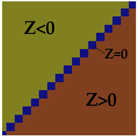
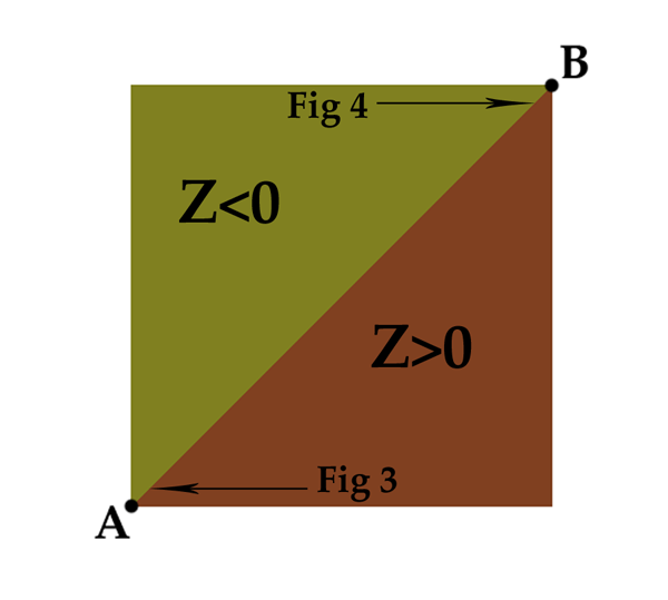
So, if we have two triangles that share an edge (as most triangles do in video games), and we apply the above tests to them, we should be able to accurately determine which triangle a line lays on. Figure 2 shows two triangles, and the results of performing the test (Z<0) on the line AB that defines the edge they share. It’s a nice clean mathematical split.


Figure 2 – The line from A=(0,0) to B=(5000,5000) separates points P in this region into two triangles based on the sign of z of the cross product APxAB

A fairly standard button layout
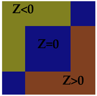
Figure 3 – In the region x and y from 800.0 to 800.001 there are indeterminate regions between the triangles.

Of course the obvious problem with this test is for points that lay on the line between the polygons, where Z=0. In our pure mathematical world, a line is an infinitely thin region between the polygons. But in the practical world of floating point, the reality is rather different. If you zoom in on the line, down to the level of the individual float regions I described earlier, you will see the line defined by Z=0 is comprised of a series of regions (figure 3). What’s more, if you zoom in on the same line, but further from the origin, you see that the size of these regions increases (figure 4).

The result of this could go two ways, depending on how you implement your logic. If you started out saying “Z>0 implies the point if to the left of the line” , then all the floating point regions that are ON the line (Z=0), will show up as little holes, regions where the collision fails. The quick solution here is to change the test to Z>=0. This eliminates the problem of holes, but creates a new problem, the regions on the line (Z=0) are now shared by both triangles.

A fairly standard button layout
Figure 4 – Different points on the same edge, x and y from 4800.0 to 4800.001

This can create problems if the collision routine returns a list of all the triangles it detects a collision with. The logic might not be set up to deal with being in contact with two different surfaces in the same logic frame, leading to problems like sound effects being stuck on, or events failing to trigger. More commonly though, a line-environment collision test is set to return the closest collision point. Since both polygons will return the same point (which as we see is actually an overlapping region), then the polygon detected will be determined by the order in which the polygons are tested.

Historically the polygons would usually be tested in the same order, however with the increasing prevalence of multi-core architectures, it’s increasing common for programmers to implement some kind of data level parallelism, where the order in which the individual polygons are tested is not guaranteed, and will vary based on the way additional tasks are using the cores, and by the state of the memory cache, which varies from frame to frame. The result can be that the same collision test performed on the same data can return either of two polygons in a seemingly random manner. Most likely it will return one polygon 99.99% of the time, with the other polygon cropping up extremely rarely. This can result in a “Heisenbug” , which can be incredibly difficult to track down, since it surfaces vary rarely, the conditions can be impossible to replicate, and introducing test code can “fix” the problem.

There are a number of solutions to this. You can change your multi-core data sharing algorithm so that polygons that might share an edge are always submitted in the same batch. That would still leave you with the potential problem of two polygons being returned with the same collision point. You could also try to guarantee that the regions on the line Z=0 always belong to one polygon of the other, which you could do by flagging the edges of a polygon so one side uses Z<0 and the other effectively uses Z>=0.

SUMMARY

Floats are a very useful way of representing numbers. But remember that they do not perfectly represent the mathematical world that you use when creating algorithms. Floating point coordinates represent regions in space rather than points. Those regions get a lot bigger as you get further from the origin, and eventually create noticeable artifacts such as jittering and visible seams. This is an important consideration if you are attempting to scale an existing engine to one that supports a much larger world. Floating point inaccuracies can lead to indeterminate boundary regions of variable size. These need to be dealt with explicitly to avoid Heisenbugs.

References:

Wikipedia floating point entry: http://en.wikipedia.org/wiki/Floating_point
Christer Ericson, Real Time Collision Detection, Chapter 11: Numerical Robustness. Morgan Kaufmann, 2005.
Peter Freese, Game programming Gems 4, Chapter 2.3, Solving Accuracy Problems in Large World Coordinates , Charles River Media, 2004

Trends in Game Programming

Filed under: Game Development,Inner Product — Mick West @ 5:01 pm

This article was originally published in The Inner Product column of Game Developer magazine, September 2006

The job of a game programmer has been constantly evolving since game programming began its commercial existence sometime back in the 1970s. The primary factor driving that evolution has been the exponential increase in the power of game platforms, particularly consoles.
Market forces have also influenced the evolution of game programming. The increase in the size of the game market, the subsequent diversification in the gaming audience, and the emergence of mobile and casual games have significantly impinged upon the traditional image of the work that a game programmer performs.

I’ve noticed a few interesting trends in game programming emerging over the past few years, which are worth reflecting on because any game programmer who want to advance their career, and any studio head who wants to make money, needs to anticipate and plan for what will be expected of them in the years to come.

CONTENT-DRIVEN DEVELOPMENT

Historically, programmers have been the primary bottleneck in the game production process. Frequently, large sections of game code have to be written from scratch, and significant portions of the game logic are either implemented in code or need to have code written to support them. This has meant that development schedules depended heavily on the programmers, as they were basically implementing the game.
But lately, the development of a game seems to be more heavily driven by the creation of content. The role of technology””and of game programmers””has shifted from implementing content to providing the tools for others to implement content, resulting in a trend that is causing a shift in scheduling. The programming of new features now happens toward the front of the schedule. Additionally, this change is increasingly relegating programmers to a supporting role toward the latter parts of a project.

The shift to content-driven development has essentially created a new breed of engineers: technical content creators, or more specifically, technical artists, technical level designers, and script programmers. The technical artists and level designers have to operate within a complex set of technical constraints, while also understanding the technology enough to leverage all it has to offer. They may be tasked with work that’s very much like programming.

Script programmers have a differently focused skill set compared to regular programmers. They have very little focus on algorithms and data structures, and instead focus on event handling and implementing state-driven behavior.

EPISODIC CONTENT

Ubiquitous high-speed internet connectivity has made episodic content a market reality. While the change is hampered by market inertia and piracy concerns, it is inevitable that the game industry will move to a system of content delivery that’s free of physical media, as has already happened in the casual games market, where nearly every game is sold online. The trend is also sweeping over the full price PC game market.

This prevalence of downloadable media naturally encourages the development of episodic content””content extends a game without being an entirely new one. The prime use of episodic content is to add extra levels, chapters, goals, missions, or stories to a game.

Since this additional content will consist mainly of data (models, levels, scripts, audio), the role of the programmer will be limited to providing the initial framework that allows for the additional content to be seamlessly incorporated into the game.

Episodic content will further advance the trend in content-based development. With a sufficiently robust base engine, a game might extent its series by several years without requiring any extra traditional coding, the only programming being executed at a high level via the technical content creators, particularly script programmers.

MULTI-THREADED PROGRAMMING

Probably the most dramatic change in technology from a programmer’s point of view is the forced shift from single-threaded engines to multi-threaded ones. The next generation of consoles all have multi-core processors, and the majority of PCs aimed at gamers released from 2006 onward will have some kind of multi-core processor.

While a multi-core architecture is going to be the norm, the majority of game programmers are still unfamiliar with the techniques of multi-threaded programming. In addition, tools for debugging and profiling multi-core code are still in their infancy. In a complex engine with many interacting systems and many patterns of memory access, the task of optimizing for multiple cores is going to remain something of an art form for several years.

Generally, the trend here is toward more and more cores on a single chip. Long-term trends point to 8, 16, 32, and more cores on one chip. Understanding the concepts of data level parallelism, Amdahl’s Law, and pipelining will become a game programmer’s core skills.

PROCEDURAL CONTENT

A decade ago, artists created their 3D models one polygon at a time. Eventually, modeling tools grew more sophisticated””yet most artists still deliver assets that are essentially just a bunch of triangles with materials.

An increasing trend is the creation of 3D objects in a procedural manner via a mathematical model of that object, and a set of parameters. The classic example of this is a tree. Trees of a particular species are very similar, but no two trees are the same. If a programmer can create a mathematical description of a tree, then she or he can generate an infinite number of varied trees.

Procedural content can either be pre-generated (essentially, used as an exotic modeling tool), or generated at run time, so the designer can simply say, “Forest here,” without having to specify the look and position of each individual tree.

As environments become more realistic, a much large portion of the models used in the game will be generated using some form of procedural content. Technical artists will be responsible for generating the archetypes of particular objects (and textures, animations, and even sounds), and then designers or other artists will tweak the parameters to create a specific instance or allow multiple instances (like a forest) to be created.

The challenge of the programmer within this trend is to provide the tools to allow the artists to work effectively and intuitively with the technology. Programmers are not artists, and the sooner an artist can start using the procedural technology in a non-technical environment, the better the results.

EMERGENT GAMEPLAY

Originally, game programmers would program exactly what went into a game, and they would understand exactly why a certain thing happened at a certain time under certain conditions. The amount of code and data involved was reasonably small, and usually the behaviors of game entities were hard coded by, of course, coders.

Now, it’s more typical for the behavior to be determined by data set up by a designer, and involve the interaction of many complex systems. The programmer creates the technology to simulate an environment, and the game designer places objects in it and created gameplay by influencing the behavior of those objects in a variety of ways.

Thus, instead of the behavior of the game being specifically coded in, it now emerges from a large number of variables””and it’s no longer always clear why certain things happen in the game. Debugging becomes more difficult, and programmers often find it painstaking get the game to behave exactly as they want.

This trend, overall, is showing how game development is leaning toward a softer form of content creation, where (for example) non-player characters are inserted into the game with a set of very high-level directions and a sufficient level of underlying logic to handle all eventualities. The actually gameplay that emerges is not always clear at the outset, and will not be directly coded by the programmer.

But the challenges here lie in debugging the inevitably fuzzy mess. Avoiding performance issues may also be a problem, as layer upon layer of behavior modifiers may be added to push the behavior in the desired direction. Programmers and designers must work together to know when it is appropriate to write new code rather than modify the behavior via tweaking the data.

PROGRAMMABLE GPUs

The rate of increase in power of video cards aimed at PC game players has outstripped Moore’s Law. By some measures, the processing power of the GPU can greatly exceed the power of the CPU. With this shift in power, an increasingly large amount of work can be done on the GPU, and not just rendering graphics.

The highly parallel nature of modern GPUs makes them very suitable for tasks that exhibit a high degree of data-level parallelism, where many individual chunks of data (such as a rigid body) have the same code executed on them independently (such as physics-based motion and collision resolution). Using the GPU for non-graphics related tasks is referred to as general purpose GPU, or GPGPU.
From an engine programmer’s point of view, the major challenges associated with this trend are managing the flow of data between the CPU and the GPU, and implementing the required logic in the restricted instruction set of the GPU.

MUSCLE-DRIVEN ANIMATION

A specific example of procedural content is muscle-driven animation, in which the motions of the game’s characters are driven by an accurate physics-based model of bones and muscles under the characters’ skin. Animations such as running and jumping are not pre-created by an animator, but instead are generated in real time, based on the physical state of the character and the interaction with the environment.
Doing this accurately requires a significant chunk of processing power, and so has not really been utilized very much in games. Even in the pre-rendered world of Hollywood CGI, much research is still being done to make this technology look good, even for relatively straightforward tasks such as running over variable terrain.

Muscle-driven animation is also the ultimate goal of facial animation, leading to lifelike and infinitely varied facial animations, which can also link directly into a speech synthesis system.

Again, the challenge programmers face with this new technology is how to provide the tools that allow technical animators to define the archetypical motion models and parameter sets, and then allow the less technical artists and designers the creative freedom to fully utilize the muscle-driven animation system.

NOVEL CONTROLLERS

On the PC, you have a mouse and a keyboard, sometimes a joystick. On a console you have a controller, included with the console purchase. For the vast majority of game players, the interface between their brains and the game has been fixed and consistent””and relatively simple, being just a two-axis analog control, and some buttons.

Three trends in technology are driving change here. First, newer consoles are shipping with motion sensing controllers. Most notably Nintendo’s Wii, with its revolutionary controller, opens up a whole new set of challenges for the programmer.
The technical challenges of working with a motion-sensitive device are to provide mapping between the user’s actions in manipulating the controller and game’s actions. Since the 3D motion of the Wii controller is a dimension more complex than the simple analog sticks and buttons of previous generation controllers, it will be quite some time before programmers really come to grips with all the ways this new technology can be used.

Second, there has been an increase in the number of “pointer” games, where the game action is controlled by mouse or stylus movements in a 2D plane, and the user is either pointing and clicking or drawing actions on the screen. This trend in control technology is driven by the Nintendo DS, but also by the casual games market. Since the Wii controller can function as a pointer, this type of control technology may also crop up in several games for that platform.

Third, Guitar Hero, Dance Dance Revolution, and Donkey Konga have shown that games can be packaged with a very inexpensively produced, game-specific controller, and be wildly successful. Each type of new controller presents new problems for programmers as they attempt to provide intuitive ways of translating the raw data from the controller into something representative of the player’s intentions.

The Sony EyeToy also represents something of a trend here with its own set of problems, namely, the idea of incorporating live video of the player into the game as a control element. This technology is still in its infancy, and the fiddly nature of setting up a video camera as a controller suggests it’s unlikely to achieve extensive usage.

The most likely use of camera is in-game chatting. I predict that people will attempt to incorporate some kind of facial expression recognition into their games (imagine a poker game that could tell when you are smiling, so you really have to maintain your poker face). The AI required for effective video processing is still unsuitable for games, but it’s an exciting avenue for the games of the future.

SPEECH GENERATION AND RECOGNITION

A game feature that’s closer to becoming common is voice control. The Nintendo DS is broadening the popular appeal of this with Nintendogs, which incorporates simple speech recognition into the game. It’s relatively simple for a game to use single word commands””even most mobile phones now have some form of voice recognition.

But beyond recognition of single words, the great leap forward in this trend will require leaps and bounds in natural language programming. Eventually, players will be able to hold simple conversations with characters in a game, or characters in a game will be able to synthesize conversations between themselves. This technology will inevitably appear in titles like The Sims, but it is unclear when the technology will mature.

GAME AS PHONE

Computers and game consoles can now be used as communication devices. Sometimes, this takes the form of online chatting or instant messaging. Sometimes it’s full voice and video communication over the internet, which may be incorporated into gameplay. Online games on next-generation consoles offer buddy lists and chatting by default.

As well as the more obvious challenges posed by this technology, the use of games as communication devices has the potential to greatly increase the emphasis on reliability and usability of the game.

Users develop a very strong expectation that their phones will not crash or pause, and this translates to a strong expectation that the game will not crash or interfere with communication. In a single player game, a game crash is very annoying, but in a multi-player experience, it is much more annoying, as you are ripped out of real-time communication with real people. This increases the programmer’s focus on reliability and a fluid user interface.

CONCLUSION

The complex interplay of technology, market forces and innovation in game design makes it impossible to project trends more than a few years in the future. Certain technological developments (more CPU cores, more memory) are inevitable, but that’s only part of what is driving trends in game development.

Ten years ago the Playstation One had only been out a short while and the industry was in the midst of a shift from 2D to 3D games. Much of what occurred during this shift was a gradual evolving from one game to the next. This seems like an inevitable progression, given the benefit of hindsight, but at that time the future of game development was as much in flux as it is now.

The evolution of game development is just that, an evolution, driven by the invisible hand of the market and shaped by periodic seismic shifts in technology and game design. While it is impossible to predict exactly where this will lead, or how quickly, the wise game programmer would do well to occasionally pay attention to where it seems to be heading.

Shattering Reality

Filed under: Game Development,Inner Product — Mick West @ 4:48 pm

How it is impossible to model reality, and how we will always be faking it.

Programmers and game designers sometimes start out a project with the noble intention of making the most realistic game possible. But as they progress, they discover that their initial dreams of realism are somewhat difficult to implement in a practical manner. Firstly, in the area of player control, the most realistic physics is often not the most enjoyable physics. Secondly, in the area of non-interactive effects such as explosions, smoke, etc, the programmer quickly finds that trying to accurately simulate the underlying physics is computationally infeasible.
This article discusses the problems of simulating reality, with particular reference to shattering glass.

INVESTIGATING REALITY

Shattering glass is used in many games. The most obvious use is a glass windows in shooters, where the player can shoot the window, leaving either a bullet hole, or shattering the whole window. But it is also used in other types of game where increased realism can benefit the game. In racing games, the car windows and headlights shatter in a crash. In basketball, the backboards sometimes shatter. Even in wrestling, a realistic looking fluorescent glass tube being smashed over your opponent’s head, can add to the feeling of immersion.

Suppose you, the programmer, have been tasked with making the glass shattering effect, and your producer has told you to make it “as real as possible” , how should you proceed? Well, perhaps the first thing you’d do is go and read some physics books, and do some searches on the internet, and try to find some physical models, some equations, that describe how glass shatters in the real world.
The first problem that you run across when trying to implement a “real” physical effect such as shattering glass, is that for a lot of these effects, nobody actually knows how they work in the real world.

Take another common effect: simulating fire. Nobody knows how the underlying physics of fire really works. Something as simple as a candle burning is a complex interplay of molecules, gravity, chemical reactions, and the heating, motion and radiation of multiple gases, liquids, solids and plasma. Since physics has yet to explain exactly what is going on when something burns; rendering an accurate image of the candle is an inexact task, involving light emitted from the burning gasses, reflected off the wick and the wax (both liquid and solid), transmitted and scattered through the solid wax, refracted through the pooled liquid wax, refracted through waves of rising hot air and vaporized paraffin, absorbed and reflected off the smoke particles and interacting with the rest of the environment. And that’s just for one candle, imagine if you had a whole cathedral full of them.

Similarly, scientists simply do not know how glass shatters. There are competing models of what is going on when a piece of glass breaks into two pieces. The debate is whether the fractures happen via the breaking of sub atomic bonds one after the other in the direction of the fracture, or if the fracture follows the formation of microscopic cavities that form ahead of the fracture tip. [1]
Unfortunately, while interesting, these distinctions are entirely academic to the game programmer. If you’ve gone as far as discovering this in your research, then you’ve probably gone too far, some things can never be simulated.

LIMITS TO COMPUTATON

The real world operates at a much finer grained level then is possible to simulate on a computer. The “real world” operates at the molecular, atomic and sub-atomic level. The so called “rigid bodies” that modern physics engines simulate are actually composed of septillions (1 septillion = 1 billion billion billion billion) of molecules, and it is the interactions between these molecules that create the apparent motion of the rigid body. In addition the time-step (or “main loop” ) of the real world operates in an essentially infinitely small step of time, compared with the 1/60th of a second that many game physics systems run at.

In last month’s article, I described simulating a “blob” with a mass-spring system. In the real world solid matter actually works a little like my blob, except that there are vastly more masses (molecules), an additional order of magnitude more springs (inter-atomic and inter-molecular forces), and a significant number of the springs keep breaking and re-forming.
So, if we want to simulate something as straightforward as a bullet going through a glass window, with the aim of it looking realistic, then what we can’t do is simulate the interactions of the 10^28 silicon molecules, with quintillions of simultaneous micro-fractures resolving into the macro fracture pattern we want.

Glass contains a lot of molecules. The most accurate simulation would simulation the state of each molecule, and the interactions between molecules. Even forgetting that we don’t actually know what is going on at the molecular level. The sheer number of molecules in matter is infeasibly huge. In a single gram of a material like glass, there are approximately 10^25 molecules. Even ignoring the physical limits of computing, Moore’s law will still require about 100 years before we’ll have enough computing power to even store the state of the simulation.

Still, much research has been done into precisely that type of simulation, albeit on a greatly reduced scale. It is still possible to simulate what is happening within a material using a molecular model, simply by making the molecules a lot bigger, so you don’t have to use as many of them. Results seem to be very realistic, but are still rather expensive. In 2002 ,the ASCII White, 12 teraflop, $110 Million, supercomputer ran simulations of fractures in a small cube of material with 1,000,000,000 (one billion) molecules, taking nearly two seconds per frame [2]. By comparison, the Sony PS3 has a theoretical performance of two teraflops, and it needs to do a lot more than simulate one crack.

So this hyper-realistic style of simulation is not yet feasible for video games. Hence we must move on to looking at models of the interplay of forces within the object that are much cheaper to implement. Realism must begin to take a back seat to another type of realism – the reality of our limited resources.

PRACTICAL SHATTERING

How quick does the shattering code actually have to be? Well, there are two main performance problems with shattering.
Firstly, shattering happens very fast. Cracks propagate in a material at about the speed of sound in that material. For glass, that’s around 5000 m/s. If simulating at 60 fps, then that means that any shattering of glass is effectively instantaneous. This then means that the entire calculation has to happen in a single frame.

Secondly, the shattering of an object turns what was a single piece of the environment, or a single rigid object, into hundreds of individual rigid objects, each requiring memory and CPU resources. If the player is given the freedom to shatter everything in sight, then how do we stop them exhausting system resources? Even in older games where the fragments vanished after a period of time, a common trick of games testers was to try to crash the game by shattering multiple objects at the same time, especially in split-screen mode.

What to do about the fragments generated is a problem with multiple solutions. You can devote a very large amount of your resources to these chunks (assuming it’s beneficial to the game somehow). You can make the chunks vanish after a period of time, or remove old chunks as new ones are generated, perhaps with some priority system. That’s more of a game design issue than a programming issue.
The problem of the time used in the generation of these chunks or fragments is another matter. If the shattering takes a long time, it can cause the game to glitch perceptibly. Players will be familiar with many games that slow down when a large amount of things are blown up. This can be due to an excessive amount of graphical effects on screen, but in more recent games this can also be due to increased physics complexity in the arena. Adding accurate shattering to the mix has the potential to greatly increase the amount of slow-down in such situations.

In order for the game not to slow down perceptibly, the shattering code must be able to shatter several objects per frame. Let’s say we can share the shattering over a few frames if we happen to have a large number of objects shatter simultaneously. Then a reasonable number would be perhaps ten objects shattered per frame, which must incur no additional overhead to the frame’s processing load. This essentially means we have to have some processing power kept permanently in reserve for this kind of thing. You’d probably not want to budget more than 10% of your processing for such frivolity as shattering objects, so that means each individual shatter must happen in less than 1% of a frame, or about 0.16 microseconds.

We can look at this another way. Assuming that the shattering effect is going to create a large number of rigid bodies that were not there before, then the system is going to have to be able to simulate and render those bodies without dropping speed. So all we have to do is to make it so that the shattering code for an object does not take longer than the simulation and rendering code for the rigid bodies that are generated by that shattering. However, this might not be true if the shattering of the object and simulation of resultant rigid bodies use different resource – such as when the shattering happens on the main CPU, and the simulation is on another processor such as the SPU, PPU or GPU.

BEYOND MOLECULES

The next step is to try to model the physical forces acting on an object at an event higher level, using something like a mass-spring system. We can devolve the object into a system of connected points as a mesh of triangles (or tetrahedrons), and then model the propagation of forces through this mesh, and allow object to split along lines or planes when the forces at that junction surpass a certain level.

Even a highly abstract simulation of shattering can be very time consuming. At the Game Developers Conference in 2002, O’Brian and Hodgins presented a method of 3D shattering using this kind of decomposition into tetrahedrons [3]. Their example of a single small wall took an average of 399 minutes to calculate a simulation of one second of shattering, based on 1999 hardware. Updated by a factor for twenty to 2006 hardware, this still only gives us about 1/1000th the speed of a real time simulation.

BEYOND PHYSICS

The problem with simulating physics is that, while we know what result we want to get, the physics model does not always supply this result, and it takes a long time to not supply it.
Instead, we can try to shatter glass based on purely aesthetic concerns. We can observe how glass breaks, and then try to duplicate it with simple heuristics.

Kadono and Arakawa used high speed cameras to study crack formation in a sheet of glass [4]. Other people have observed some consistent things about the way glass breaks when impacted by a small objects. Observations generally indicate the following simple rules:
1) Radial cracks propagate from the impact point like spokes on a wheel.
2) Other cracks propagate between radial cracks, like a spider web.
3) Cracks stop when they hit each another crack
4) The size of the glass fragments is a power function of the distance from the impact point.

These observations suggest a number of simple algorithms we could try. Since we are essentially generating a visual pattern, no physics need be involved, and we can use a number of “cheats” to get the result we want. In this case we can essentially generate the “spider web” pattern by:

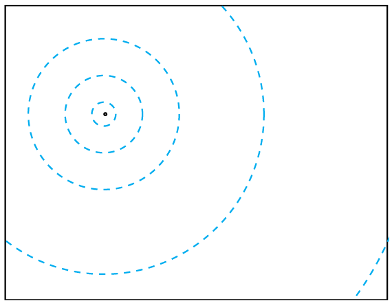
1) Imagine a framework of concentric circles, centered on the impact point, with the distance between them increasing exponentially. (figure 1)

2) Create jagged radial cracks by joining roughly equally spaced points on these circles in sequence from the center to the edge. (figure 2)

3) Create traverse cracks by joining sequential points on the circles (figure 3)

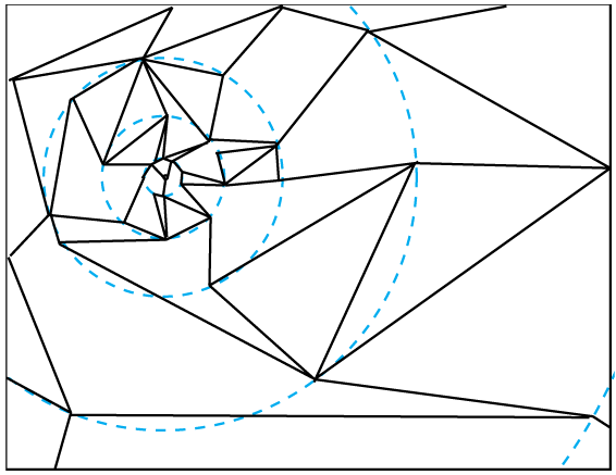
4) Turn the resultant quads into triangles by randomly splitting them along either diagonal. (figure 4)

Now that’s a very simple algorithm, and it’s very fast. It will even give you a reasonable result for some types of glass and some type of impact.

There is lots you can do to extend it. You can add various types of random perturbation to make it look less regular. You can randomly join together adjacent triangles to create jagged irregular pieces (figure 5). You can let the radial cracks bifurcate. You could either arrange the line generation so there is no possibility of the cracks crossing (by limiting them to a angular segment), or you could allow your cracks total freedom, and have an additional step to detect and resolve crack-crack collision.

SUMMARY

Simulating the underlying physics of something that is essentially a cosmetic effect is often inefficient and does not always give satisfactory results. Simulating at any kind of molecular level is infeasible. Simulating as a system of joins and forces can give reasonable results, and much work is being done in this direction. However, you can still get a perfectly usable result by simply observing what is going on, describing it, and then simulating your description, without any need for understanding the underlying physics. Since your model is based purely on the visual results, it has the potential to look more aesthetically pleasing than a physics based solution.

References:
[1] Mills, W. What Makes Glass Break?, Research Penn State Magazine, October 31, 2005, http://www.rps.psu.edu/probing/glass.html

[2] Abraham, F. Simulating materials failure by using up to one billion atoms and the world’s fastest computer: Work-hardening , Proc Natl Acad Sci U S A. 2002 Apr 30;99(9):5783-5787. http://www.pnas.org/cgi/content/full/99/9/5783

[3] O’Brien, J. F., & Hodgins, J. K. (1999). Graphical Modeling and Animation of Brittle Fracture. ACM SIGGRAPH 99 (pp. 137-146). Los Angeles, California: ACM. http://www.cs.berkeley.edu/b-cam/Papers/obrien-1999-GMA.pdf

[4] Kadono, T, & Arakawa, M, Crack propagation in thin glass plates caused by high velocity impact, APS Physics Review, March 2002.

Blob Physics

Filed under: Game Development,Inner Product — Mick West @ 1:57 pm

This article was originally published in the “Inner Product” column in Game Developer Magazine, May 2006

USING VERLET PHYSICS TO SIMULATE BLOBS

Download the blob code and executable:
DOWNLOAD
91K

Games such as Gish from Chronic Logic on the PC and LocoRoco from Sony on the PSP use a 2D physical simulation of a blob as the main character. The physics behind this blob provides the main basis for the gameplay within these games. Since the focus is heavily on gameplay, the actual physics has very little relation to reality, and is not the kind of thing you find covered in books on game physics. This article sets out the basics behind one method of 2D blob physics, and discusses some of the practical implementation issues. I also provide full source code and a demo program for a working blob system.

MASS SPRING SYSTEM

Both games mentioned use a model that has been used for decades; a “mass spring system” . This is simply a collection of point masses connected by a series of springs, roughly in the shape of the object you desire. You can think of it like a particle system, where each particle is attached to some other particles by a number of springs. See figure 1 for a simple example.


Figure 1 – A simple mass-sping system with three masses and three springs

A simple spring connects two points, and has four basic parameters.

1. The rest length, which is the length of the spring when it is neither stretched not compressed
2. The minimum length of the spring when fully compressed
3. The maximum length of the spring when fully extended
4. The force exerted by the spring, proportional to its displacement from the rest length

Some springs can exert a different force depending on if they are compressed or stretched. The force can also vary in a non-linear relationship with the displacement, but for our purposes, the simple spring described above works well, and is easy to use.

A simple point mass has three parameters
1. The position in space, expressed as a 2D vector
2. Its previous position
2. Its mass

For most of what we are doing, I use a mass of 1.0 for all the point masses. However it’s useful to have a per-point mass, as it makes it easy to try various effects. If you end up with all the masses being the same, then you can obviously optimize this out of the computation.

VERLET MADE EASY

Verlet Integration is a fancy name for a slightly different way of applying the velocity and acceleration of a point to its position. Normally a point P will have a position X and a velocity V. Forces act on the particle, namely gravity, air resistance and the springs. The traditional (non-Verlet) way of updating the position of a particle is to first update the velocity with the acceleration and then update the position with this velocity:

F = total of forces acting on this point
T = Time step to update over
V += T*F/M
X += V*T + F/M/2*T*T

This generally referred to as Euler integration (with a second order Taylor series correction), but you might recognize it as the standard Newtonian equations of motion, (more usually notated as v=u+a*t and s=u*t+1/2*a*t*t). While referring to this as “integration” is technically correct, and will lead to a deeper understanding eventually, don’t worry if you don’t follow what is meant by “integration” – just think in terms of the equations of motion.

Verlet integration is basically another way of performing this physics advancement step. With Verlet we do not store the velocity, instead we store the previous position, and the velocity is implied as the difference of the current position from the previous position. The physics update then becomes:

F = total of forces acting on this point
T = Time step to update over
X0 is the previous position, X1 is the current position
XT = X1
X1 += (X1-X0) + F/M*T*T
X0 = XT

So why use Verlet, well technically using Verlet integration is more accurate than using Euler integration when the forces vary along with position and velocity. The reasons why this is so are a little obscure, and for many practically game purposes this difference in accuracy is not a major issue. The main reason for using Verlet is that it makes it very easy to apply constraints to a physical system. When a point moves past a physical limit (such as one point moving further away from another point than the maximum length of a spring that connects them), then we can simply move the point back to a “safe” position within that length. There is no need to calculate an impulse velocity, as the velocity is implied in the position, and is automatically handled by the movement.

BUILDING A BLOB

Once I got the basic spring-mass system working, I needed to create a blob. I figured that since the natural shape of a body of water is a sphere (when subjected to neutral external forces, such as a rain drop, or a blob of water in zero gravity), then I should start with a circular spring mass system, and then the application of gravity would naturally deform it into a nice blob shape.


Figure 2 – A single skinned blob, suffers from an easily folded skin

So my first attempt (figure 2) was a circle of 20 point masses, each joined to each other , and to a center point by springs. This is a standard N-gon, with the rest lengths of the springs being the natural lengths of the sides of the N-gon. This worked reasonably well for a first pass, and gave me something vaguely blobby that settled into circle under zero gravity, and deformed a bit when resting on the ground under gravity. But it suffered from several problems:
”¢ The “skin” of the blob (the lines around the edge) kept folding over themselves, leading to ugly spikes in the skin.
Ӣ The blob was either too wobbly, meaning the edges of the blob wiggled like a giant piece of Jello, or too stiff, meaning it looked like a rubber ball.
Ӣ It kept getting caught on things, the outer edges would wrap around a corner of the environment, and the blob would hang there, looking like a dishrag.

My first attempt at solving this was to make the inner springs (the “spokes), have a longer rest length, so they would be under compression, and have the outer springs (the “skin” ), have a shorter rest length. I was thinking this would simulate surface tension. However, this did not work very well, the shape did not improve, and the blob tended to violently collapse if gently nudged.

A BETTER BLOB

So I decided I needed a bit more structure to the blobs to make them more stable. After a few more failed experiments I hit upon the solution. Simply give the blob two layers of skin, one inside the other like concentric circles, joined together with a fairly rigid zig-zag set of joints. The inner skin is joined to a central point as before. See figure 3.


Figure 3 – Double skinned blob, the double skin structure provides a very stable skin.

This works remarkably well. I had to tweak the constants a bit, most specifically the number of segments, the thickness of the skin, and the strength of the springs. But quite quickly I had a very realistic acting blob. See figure 4 for the blobs in action

Why does this work so well? A “blob” here is a blob of very thick and slippery liquid, something like mercury. Mercury has a negative coefficient of surface tension, meaning the “skin” of a drop of mercury has very different properties to the interior. I initially though that the increased tension within the skin structure of our new blob was in some way simulating the effects of surface tension. But after looking at it for a while, I saw that the main effect it was having was constraining the curvature of the skin, thus smoothing out the high frequency wobbles we saw earlier. It’s simulating the appearance of surface tension rather than the underlying physics.


Figure 4 – The blob physics in action with various blobs. Download the sample to see for yourself.

BLOB PROBLEMS

I encountered three major problems in implementing this system. Firstly the blobs tended to be unstable, and wobbled all over the screen in the absence of external forces. Secondly, the blobs would get stuck, especially against corners, but also against surfaces. Finally the blob edges tended to get twisted when they impacted the environment at high speed.

The first problem (instability) struck me as a bit odd, since Verlet integration is known for being a bit more stable than Euler integration. This problem had me scratching my head for a while, but I finally figured out that it was due to the order in which I was performing the updates. I was looping over all the points, gathering the forces for a point (from the springs) and then moving the point.

The problem with that was that when a point moved, the force it applied to another point via a spring would change. In the case of two points connected by a single spring, the force exerted by the spring should be symmetrical for each point. However, if you move one point before gathering the force for the second point, then the forces will be different. This causes the spring system to have a net force imbalance in a particular direction (depending on the order of update). The solution here was very simple. I just split the loop up into two separate loops: one to gather the forces, and then one to apply them in the integration step. This ensured that all forces were symmetrical.

The second problem (getting stuck) has to do with the way collisions are handled. Since the collision of a point is implicit in its last movement, then if a collision resolution causes a point not to move very much, then it effectively kills its velocity. For collision resolution of a single point mass to work correctly (i.e. bounce off the surface), the next movement must be of appropriate magnitude and direction so future movement is correct. However, we are not simulating points; we are simulating a blob, so we need to consider the movement of the system as a whole.

With a spring mass system, the compression of the springs can handle the bouncing (to a certain degree). So if the leading edge points of a spring mass system simply stop when they hit a wall, the springs connecting to the points behind them will be compressed, and eventually bounce the whole blob off the wall in a nice convincing manner.

This works fine for something that just bounces up and down, but something hitting a surface at an angle needs to slide along the wall. This was quite easily accomplished with point/surface collisions by simply allowing the point the move parallel to the wall by the distance it would have originally traveled.

Something similar was done with line/surface collisions, but instead of the points moving parallel to the surface, they move parallel to the line. This allows the blob to slide over corners.

These collision resolutions were also where I implemented friction, simply scaling the distanced moved by a constant (like 0.95) gives a relatively pleasing result. You could calculate a friction force to be applied the next frame, but it’s simpler to directly incorporate it into the movement calculation. In the demo the friction can be altered by holding “S” to become slippery, and “A” to become less slippery. Holding “S” will allow you to slip though holes faster.

The final problem was edges getting twisted. This generally happened because a point moved furthur past another point it was supposed to keep away from. Since the spring constrain only measures distance, the point is then pushed away by the spring, but in the wrong direction, causing the edge to become twisted. One it’s twisted, it does not become un-twisted by itself.

The simplest solution, and the one I implement in the demo, is to try to never move in large steps. The easiest way of doing this is to run the physics multiple times with a smaller time-step. In the demo I run it six times per frame. Even so, the blobs can get kinks in them if shaken violently.

Something that exacerbates this problem is increasing the number of segments in a blob. With a large number of segments, the skin edges are much shorter, and so more likely to exceed their constraints in a single iteration. A lower number of segments works better. I found a 40 segment blob was impossible to kink, and yet still looked almost as nice as a 80 segment blob that was much more prone to kinking.

Obviously running the physics multiple times is not ideal, as it can be quite expensive. A better solution would be to simply ensure the kinking does not happen in the first place. Perhaps by adding some kind of angular constraint to a point on the surface. Another alternative is to link surface points to their second neighbors with a rigid constraint, so if the point gets past the first neighbor, then the second neighbor will push it back into the correct position. This type of second-neighbor constraint is commonly found in cloth simulation.

RESOURCES

Thomas Jakobsen, Advanced Character Physics, Gamasutra 2001, http://www.gamasutra.com/resource_guide/20030121/jacobson_01.shtml

Erleben, et al, Physics Based Animation, 2005, Charles River Media, Chapter 8, p265.

Chronic Logic, Gish Demo, http://www.chroniclogic.com/index.htm?gish.htm

« Newer PostsOlder Posts »

Powered by WordPress